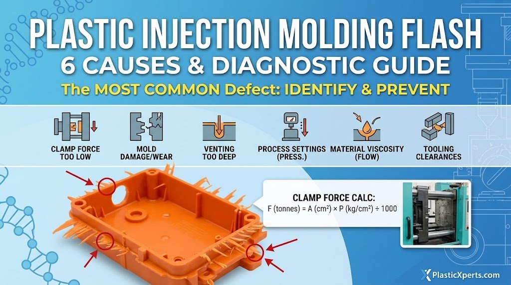
Plastic injection molding flash is the most common injection molding defect and the most expensive to ignore: it is a thin fin of material squeezed out at the parting line, and it turns a good part into scrap, a clean assembly into a hand-trimmed one, and a mold into a maintenance item.
This guide covers the six causes, how to tell which one you have from where the flash appears, and the clamp force calculation that prevents most of it before the tool is cut.
What flash actually is
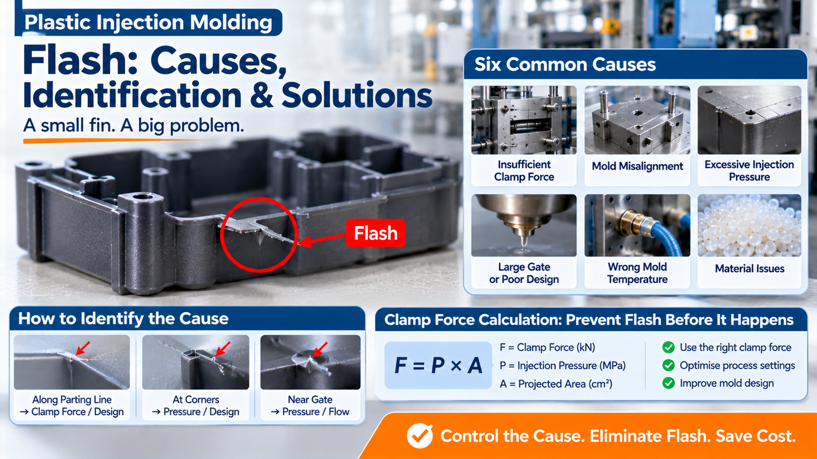
Flash forms when molten plastic reaches a gap in the tool and is held under pressure while it solidifies. That gap can be at the parting line, around an ejector pin, at a core pin, in a slide, or at an insert.
| Location | Tell-tale | Usual cause |
|---|---|---|
| Parting line, whole perimeter | Even fin all round | Clamp force too low, or mold faces damaged |
| Parting line, one area only | Local fin | Local mold damage, or uneven clamp |
| Around ejector pins | Small rings or discs | Pin clearance too large, or worn pins |
| Around core pins | Collars | Clearance too large |
| At slides | Fin along slide face | Slide wear, insufficient slide lock |
| At inserts | Flash ring at the boundary | Insert not seated, or thermal mismatch |
| At the gate | Gate blush with a fin | Gate too large, or packing excessive |
Where the flash appears tells you which of the six causes applies. This is the fastest diagnostic in molding.
Cause 1: insufficient clamp force
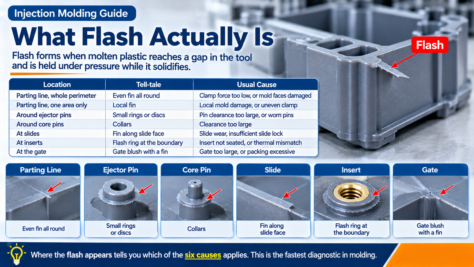
The most common cause, and the only one that is a calculation rather than an inspection.
Required clamp force:
F (tonnes) = projected area (cm²) × cavity pressure (kg/cm²) ÷ 1000
| Material | Typical cavity pressure (kg/cm²) | Typical (bar) |
|---|---|---|
| PP, PE | 300 – 500 | 300 – 500 |
| PS, ABS | 400 – 600 | 400 – 600 |
| PC, PC/ABS | 500 – 700 | 500 – 700 |
| PA, PBT (unfilled) | 600 – 800 | 600 – 800 |
| Glass-filled PA, PBT | 700 – 1000 | 700 – 1000 |
| PPS, PEEK | 800 – 1200 | 800 – 1200 |
Worked example: a 20 × 15 cm housing with a projected area of 300 cm², molded in ABS at 500 kg/cm²:
F = 300 × 500 ÷ 1000 = 150 tonnesAdd 15 to 20 percent for safety: a 180-tonne machine, not a 150-tonne one. The most common press-sizing error is using 300 to 400 kg/cm² instead of the real cavity pressure — and a machine sized on the low number flashes on every shot.
Two practical notes: the projected area includes runners and overflow, not just the part; and cavity pressure is not injection pressure — it is the pressure inside the cavity at the end of packing, typically 40 to 60 percent of the injection pressure reading.
Cause 2: parting line condition
| Problem | Symptom | Fix |
|---|---|---|
| Damaged parting surface | Local flash, repeatable in the same spot | Stone or re-cut the parting line |
| Wear from long production | Flash appears gradually, all round | Re-machine parting faces, restore land |
| Insufficient parting line land | 3 – 5 mm land needed | Rebuild the land |
| Uneven clamping surface | Flash on one side | Check platen parallelism, mold base flatness |
| Warped mold base | Progressive flash | Replace or re-surface the base |
| Dirt or plastic on the parting line | Sudden flash after a run | Clean the faces, add a cleaning routine |
A parting line is a sealing surface, and like any sealing surface it wears. In high-volume tools it needs periodic inspection and re-machining — the "flash appeared after two million shots" conversation is a maintenance story, not a process story.
Cause 3: venting that is too deep
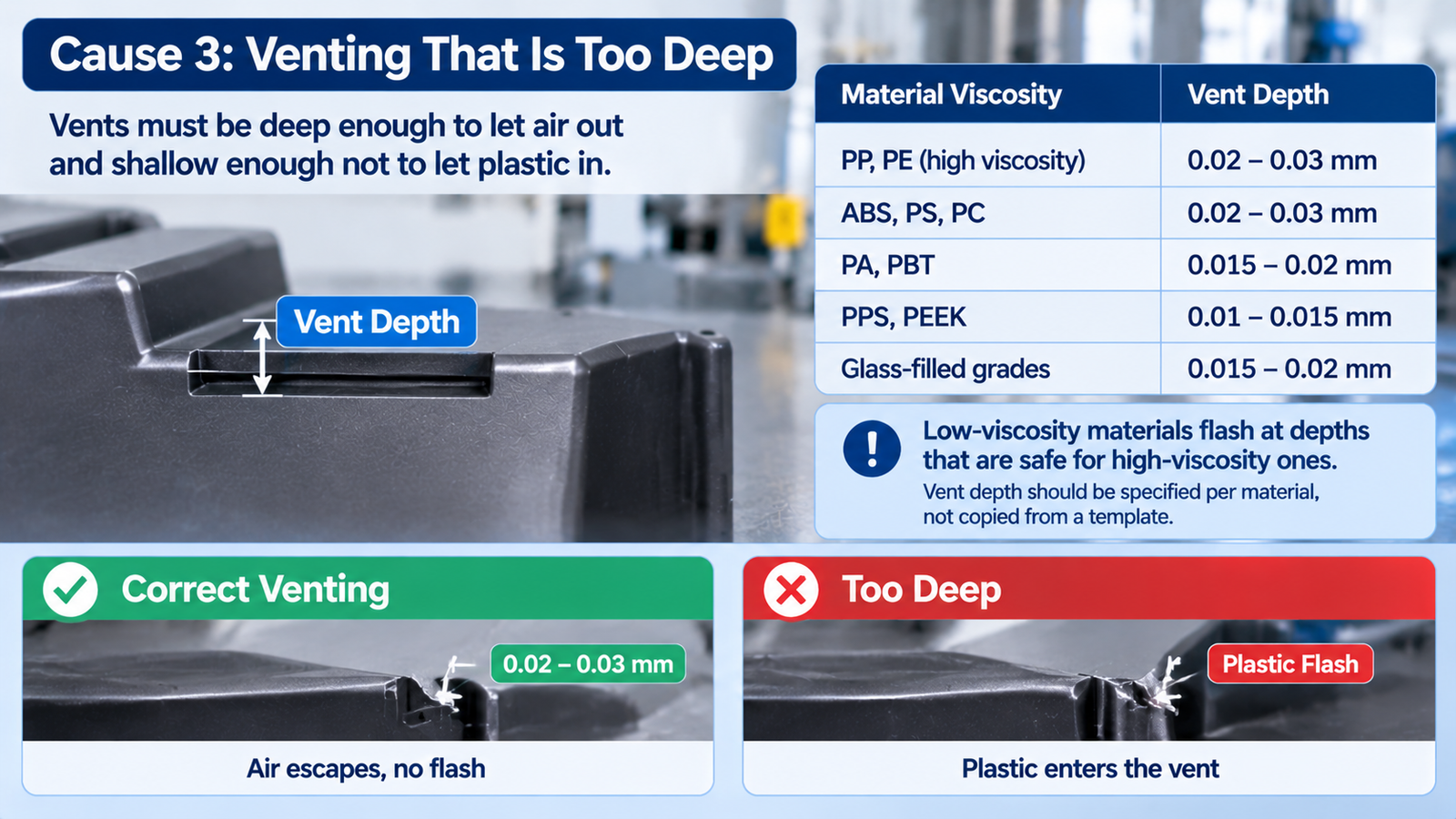
Vents must be deep enough to let air out and shallow enough not to let plastic in.
| Material viscosity | Vent depth |
|---|---|
| PP, PE (high viscosity) | 0.02 – 0.03 mm |
| ABS, PS, PC | 0.02 – 0.03 mm |
| PA, PBT | 0.015 – 0.02 mm |
| PPS, PEEK | 0.01 – 0.015 mm |
| Glass-filled grades | 0.015 – 0.02 mm |
Low-viscosity materials flash at depths that are safe for high-viscosity ones. A vent designed for PP at 0.03 mm will flash on PA66 at the same depth, because nylon flows more easily at its processing temperature. Vent depth should be specified per material, not copied from a template.
Cause 4: process settings
| Setting | Effect on flash | Direction to fix |
|---|---|---|
| Injection pressure too high | Pushes melt into gaps | Reduce until fill is just adequate |
| Packing pressure too high | Sustained pressure at the parting line | Reduce pack; shorten pack time |
| Injection speed too high | Peak pressure spike at fill end | Profile the fill, slow the last stage |
| Melt temperature too high | Lowers viscosity, easier flow into gaps | Return to the grade's mid-range |
| Mold temperature too high | Keeps material fluid longer | Reduce toward the low end |
| Insufficient cushion | Inconsistent pressure, spikes | Increase shot size |
The single most useful process test: reduce packing pressure by 20 percent and see whether the flash disappears while sink stays acceptable. If it does, the process was over-packing and the tool was fine.
Cause 5: material selection
| Material property | Effect |
|---|---|
| High melt flow rate (low viscosity) | Easier flow into gaps — flashes more readily |
| Glass or mineral fillers | Reduce flash — higher viscosity |
| Lubricant-heavy grades | Higher flow, more flash tendency |
| Regrind with degraded viscosity | Variable flash shot to shot |
If a part flashes on one grade but not another, viscosity is the reason. Switching to a lower-MFI grade of the same polymer is often cheaper than re-cutting the mold.
Cause 6: tooling wear and clearance (plastic injection molding flash)
| Feature | Nominal clearance | Failure mode |
|---|---|---|
| Ejector pin | 0.01 – 0.02 mm | Wears to 0.05+, flash rings appear |
| Core pin | 0.01 – 0.02 mm | Wear, then flash collars |
| Slide | 0.02 – 0.03 mm | Wear plus side load, flash along slide face |
| Insert | Interference fit | Thermal cycling, flash ring |
| Gate | Sized to part | Erosion enlarges it, gate flash |
Ejector pin flash is the classic high-volume failure: the pins wear, clearance opens past 0.05 mm, and every part grows a thin ring that has to be trimmed by hand. Re-pinning is cheap; ignoring it is not.
Plastic injection molding flash: diagnostic table
| Where the flash is | Most likely cause | Check first |
|---|---|---|
| All around the parting line | Clamp force or overall pressure | Clamp tonnage vs calculation |
| One side of the parting line | Uneven clamp, warped base | Platen parallelism |
| One local spot | Mold damage | Visual on the parting face |
| At the last point to fill | Vent too deep | Measure vent depth |
| Around ejector pins | Pin wear | Measure clearance |
| Around core pins | Pin wear | Measure clearance |
| Along a slide face | Slide wear or lock | Slide clearance |
| At an insert | Insert seating | Insert fit and temperature |
| At the gate only | Gate erosion, over-packing | Gate dimension |
Measurement and acceptance
| Method | Use |
|---|---|
| Visual against a signed limit sample | Production acceptance |
| Caliper or micrometer on the fin | Quantify, typically 0.02 – 0.10 mm |
| Optical comparator | Fine flash on precision parts |
| Projector or vision system | Automated inspection |
| Go/no-go gauge on the mating feature | Assembly-related flash |
Acceptance limits should be written, not implied: "flash not to exceed 0.05 mm and removable with a fingernail" is inspectable; "no flash" is not achievable on any production tool. For precision assemblies, 0.02 mm is a realistic limit; for cosmetic parts, flash is usually a visual criterion rather than a dimensional one.
Plastic injection molding flash: prevention checklist
| Check | Target |
|---|---|
| Clamp force | Calculated, plus 15 – 20% |
| Projected area | Includes runner and overflow |
| Parting line land | 3 – 5 mm, flat, undamaged |
| Vent depth | Per material, 0.01 – 0.03 mm |
| Packing pressure | Lowest that removes sink |
| Ejector pin clearance | 0.01 – 0.02 mm, checked at PM |
| Slide clearance | 0.02 – 0.03 mm, lubricated |
| Insert fit | Interference, checked hot |
| Material viscosity | Consistent lot to lot |
| Flash limit | Written on the drawing |
Related guidance
Our guides to injection molding defects cover the other defect types, injection molding tolerances covers how to write the acceptance limits, blow molding defects covers the extrusion-blow equivalent, mold assembly covers the fits and alignment that prevent parting-line flash, and common injection molding materials covers the viscosity differences between grades. The processing-window side is in PC defects, the wall-thickness side in non-uniform wall thickness, and the clamp and material interaction in strongest plastic material.
Defect and process data in this guide follows the test methods published by ASTM International and ISO, with typical values cross-checked against MatWeb and Engineering Toolbox. Processing practice reflects Plastics Technology guidance and PLASTICS industry standards, with material characterisation maintained through SPE and NIST reference data. For the process fundamentals, see injection molding.
What causes flash in injection molding?
Six causes: insufficient clamp force, damaged or worn parting line, venting that is too deep, excessive injection or packing pressure, material with too high a flow rate, and worn tool clearances. Where the flash appears identifies which one applies.
How do I calculate the clamp force I need?
Multiply the projected area in cm² by the cavity pressure in kg/cm² and divide by 1000. A 300 cm² part in ABS at 500 kg/cm² needs 150 tonnes, plus 15 to 20 percent margin — so a 180-tonne machine.
Why did flash suddenly appear after a long production run?
Tool wear. Ejector pins, core pins, slides and the parting line all wear, and flash appears once clearance exceeds the material's ability to seal. Check pin clearances and the parting-line land first.
Is flash caused by too much pressure or too little clamp?
Both, and they are the same problem expressed differently. Excessive cavity pressure pushes material into the gap; insufficient clamp allows the gap to open. Check the tonnage calculation before adjusting the process.
How much flash is acceptable?
Whatever the drawing says — typically 0.05 mm for general parts, 0.02 mm for precision assemblies, and a visual criterion for cosmetic surfaces. "No flash" is not a specification any production tool can meet.
Can flash be fixed without modifying the mold?
Often yes: reduce packing pressure, lower melt temperature, profile the injection so the last stage fills slowly, or switch to a lower-flow grade. If the flash comes from a worn parting line or oversize pin clearance, the mold needs work.
Conclusion
Flash is a gap plus pressure, and the gap is either designed (vent depth, clearances), worn (parting line, pins, slides), or opened by insufficient clamp. Calculate the tonnage, read the flash location, and fix the actual cause — because trimming flash by hand is a cost that shows up on every part for the life of the tool.
At Rui Cheng we build and maintain tools with 3 to 5 mm parting-line land, material-specific vent depths, documented pin clearances and clamp force calculated per part, under ISO 9001 / IATF 16949 processes on 80 to 1,400 tonne machines. Send us the drawing and the flash location you are seeing, and we will come back with a tool and process recommendation.