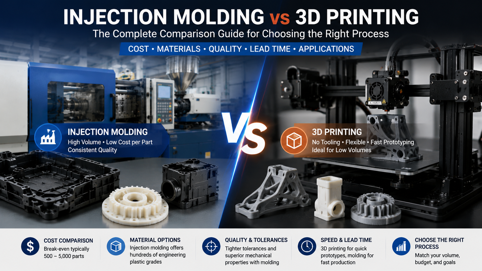
Injection molding tolerances determine how precisely a plastic part can be manufactured, and they directly affect fit, function, and cost. Buyers and engineers frequently ask: what tolerances can injection molding hold? The answer depends on material, part size, and mold quality. This guide explains standard injection molding tolerances, the factors that affect them, and how to specify tolerances that balance quality and cost.
What Are Injection Molding Tolerances?
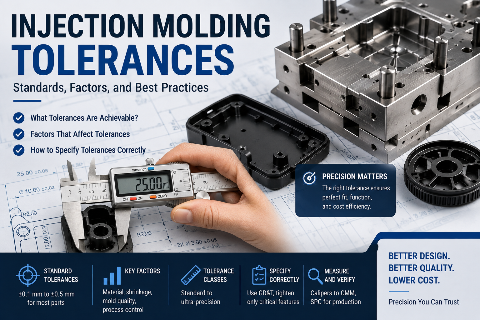
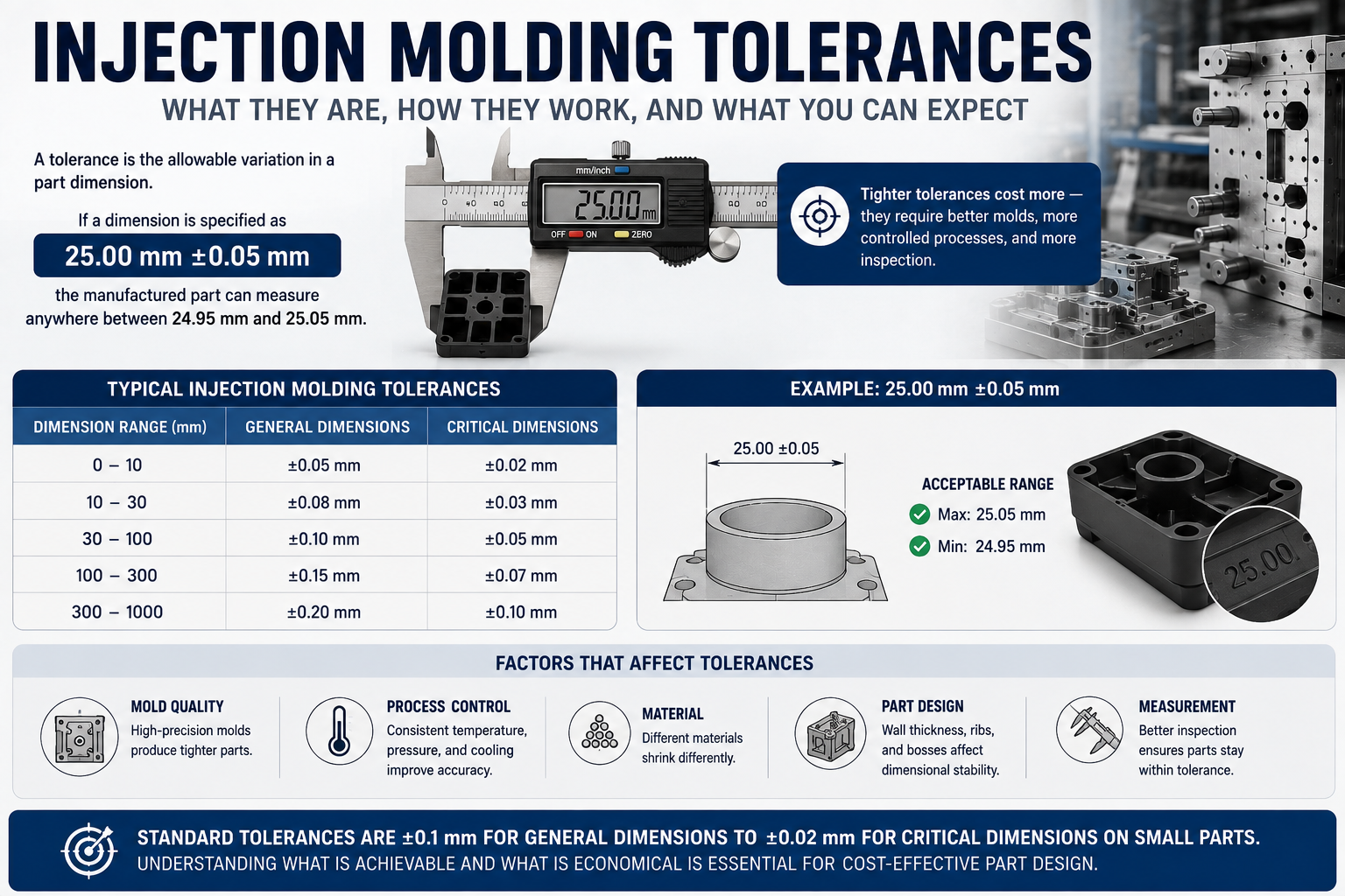
A tolerance is the allowable variation in a part dimension. If a dimension is specified as 25.00 mm ±0.05 mm, the manufactured part can measure anywhere between 24.95 and 25.05 mm. Tighter tolerances cost more — they require better molds, more controlled processes, and more inspection.
Standard injection molding tolerances typically range from ±0.1 mm for general dimensions to ±0.02 mm for critical dimensions on small parts. Understanding what is achievable and what is economical is essential for cost-effective part design.
Standard Tolerance Chart
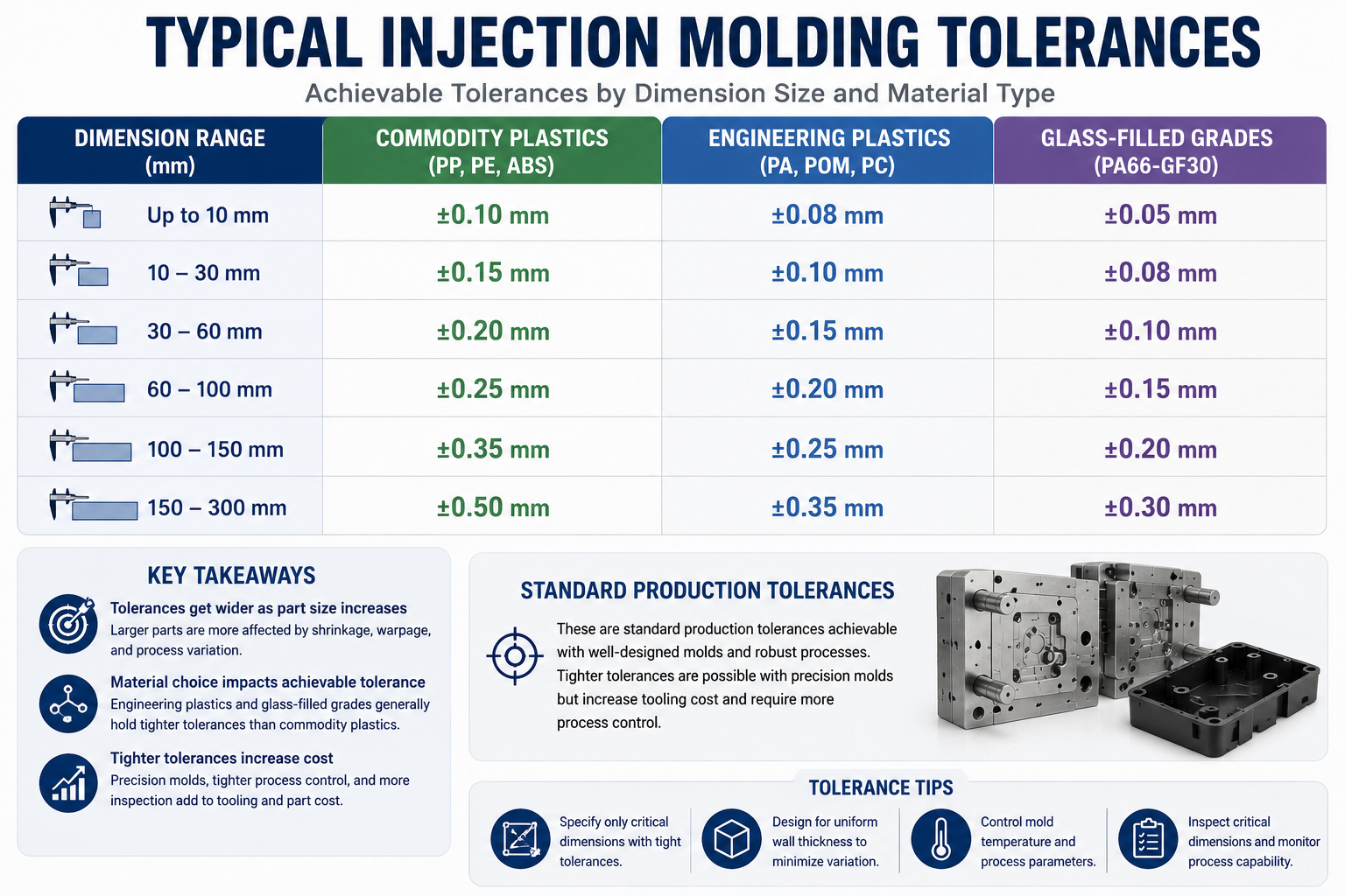
The following chart shows typical achievable tolerances by dimension size and material type:
| Dimension Range | Commodity Plastics (PP, PE, ABS) | Engineering Plastics (PA, POM, PC) | Glass-Filled Grades (PA66-GF30) |
|---|---|---|---|
| Up to 10 mm | ±0.10 mm | ±0.08 mm | ±0.05 mm |
| 10-30 mm | ±0.15 mm | ±0.10 mm | ±0.08 mm |
| 30-60 mm | ±0.20 mm | ±0.15 mm | ±0.10 mm |
| 60-100 mm | ±0.25 mm | ±0.20 mm | ±0.15 mm |
| 100-150 mm | ±0.35 mm | ±0.25 mm | ±0.20 mm |
| 150-300 mm | ±0.50 mm | ±0.35 mm | ±0.30 mm |
These are standard production tolerances achievable with well-designed molds. Tighter tolerances are possible with precision molds but increase tooling cost and require more process control.
Factors Affecting Tolerances
1. Material Shrinkage
Every plastic shrinks as it cools after molding, and the shrinkage rate varies by material:
| Material | Mold Shrinkage |
|---|---|
| Polypropylene (PP) | 1.5-2.5% |
| ABS | 0.4-0.7% |
| Nylon 66 (PA66) | 1.0-1.8% |
| POM (Acetal) | 1.5-2.0% |
| Polycarbonate (PC) | 0.5-0.7% |
| Glass-filled PA66-GF30 | 0.3-0.6% |
Materials with lower and more predictable shrinkage — like PC and glass-filled grades — hold tighter tolerances. Semi-crystalline materials (PP, PA, POM) shrink more and vary more, requiring larger tolerances.
2. Part Size and Geometry
- Larger parts accumulate more shrinkage variation across their dimensions
- Thin walls cool faster and shrink differently than thick sections
- Asymmetric geometry causes warpage
- Ribs and bosses create local shrinkage variations
- Steel quality: hardened tool steel holds dimensions longer than soft steel
- Cooling design: uniform cooling reduces warpage
- Number of cavities: multi-cavity molds have slight cavity-to-cavity variation
- Gate design: gate location and size affect packing and shrinkage
4. Process Control
- Injection pressure and hold time affect packing and shrinkage
- Mold temperature must be consistent
- Cycle-to-cycle variation is minimized with automated process control
- Humidity affects moisture-sensitive materials (nylon absorbs moisture and changes dimensions)
Standard vs. Precision Tolerances
| Tolerance Class | Typical Range | Application | Cost Impact |
|---|---|---|---|
| Standard | ±0.1-0.5 mm | General parts, housings | Baseline |
| Fine | ±0.05-0.1 mm | Precision mechanical parts | +10-20% |
| Precision | ±0.02-0.05 mm | Gears, connectors, optical | +20-50% |
| Ultra-precision | ±0.005-0.02 mm | High-end optics, medical | +50-100%+ |
Specifying unnecessarily tight tolerances increases cost significantly — tighter tolerances require better molds, more inspection, and lower production yields. Only specify tight tolerances where function requires them.
How to Specify Tolerances Correctly
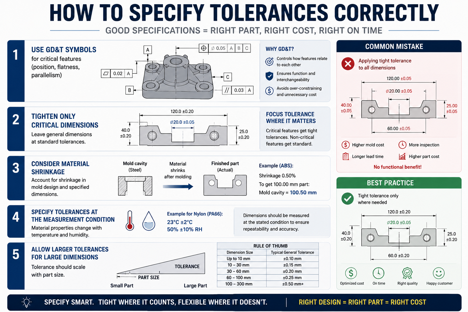
- Use GD&T symbols for critical features (position, flatness, parallelism)
- Tighten only critical dimensions — leave general dimensions at standard tolerances
- Consider material shrinkage when specifying dimensions
- Specify tolerances at the measurement condition (e.g., 23°C, 50% RH for nylon)
- Allow larger tolerances for large dimensions — tolerance should scale with part size
A common mistake is applying ±0.05 mm to all dimensions when only one or two features need it. This drives up mold and inspection costs for no functional benefit.
Tolerance Measurement and Inspection
Verifying tolerances requires appropriate measurement equipment:
| Tolerance Class | Recommended Inspection Method |
|---|---|
| ±0.1 mm and above | Calipers, micrometers, gauges |
| ±0.05-0.1 mm | Height gauges, optical comparators |
| ±0.02-0.05 mm | CMM (coordinate measuring machine) |
| Below ±0.02 mm | CMM with temperature control, vision systems |
For production runs, statistical process control (SPC) with regular sampling ensures tolerances are maintained over time. CMM first-article inspection validates all dimensions before production approval.
Common Tolerance Mistakes
- Over-specifying: ±0.02 mm on a 200 mm dimension in PP — not economically achievable (see ASTM tolerance guidelines)
- Ignoring material: specifying PC-level tolerances for unfilled PP
- Ignoring moisture: nylon parts change dimensions with humidity
- Ignoring assembly: not accounting for tolerance stack-up in multi-part assemblies
- Not using GD&T: relying on ± dimensions instead of true position and flatness
Conclusion
Injection molding tolerances depend on material, part size, mold quality, and process control. Standard tolerances of ±0.1-0.5 mm are achievable for most parts, while precision tolerances down to ±0.02 mm are possible with careful design and higher cost. Specifying tolerances intelligently — tight only where needed — delivers the best balance of quality, cost, and manufacturability.
With experience in mold design, material selection, and precision injection molding, PlasticXperts helps customers specify and achieve the right tolerances for their parts. Contact our engineering team to discuss your tolerance requirements and receive a professional recommendation.
FAQ
What is the standard tolerance for injection molding?
Standard injection molding tolerances are typically ±0.1 mm for dimensions up to 10 mm, scaling to ±0.5 mm for larger dimensions up to 300 mm. Engineering plastics and glass-filled grades can hold tighter tolerances than commodity plastics.
What is the tightest tolerance achievable in injection molding?
With precision molds and controlled processing, tolerances down to ±0.02 mm (and in special cases ±0.005 mm) are achievable for small, critical dimensions. However, this significantly increases mold and inspection costs.
Which plastic material holds the best tolerances?
Amorphous materials like polycarbonate (PC) and ABS hold tolerances well due to low, predictable shrinkage. Glass-filled semi-crystalline grades (PA66-GF30) also hold tight tolerances. Unfilled semi-crystalline materials (PP, PA, POM) shrink more and vary more.
How does tolerance affect injection molding cost?
Tighter tolerances increase cost through better molds, more process control, more inspection, and lower yields. Moving from standard (±0.1 mm) to precision (±0.02 mm) tolerances can increase part cost by 20-50% or more.
What is the tolerance for injection molded gears?
Precision gears typically require tolerances of ±0.02-0.05 mm on critical features like tooth profile and bore diameter. POM (acetal) and glass-filled nylon are commonly specified for dimensional stability.
Can injection molding hold tighter tolerances than machining?
No. CNC machining can hold ±0.005-0.01 mm, tighter than injection molding. However, injection molding produces identical parts at much lower per-part cost at volume, so the two processes serve different economics.