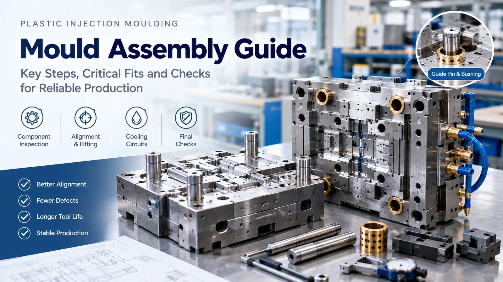
A precision-machined mould can still produce bad parts. The cavity may be cut to within microns, the core perfectly polished, and the cooling circuits drilled exactly to drawing — and the mould will still flash, stick, leak or wear early if it is assembled badly. Mould assembly is where machining tolerances become a working tool, and it is the stage most often rushed to meet a delivery date.
This guide covers what plastic mould assembly involves, the sequence that avoids rework, the fits and clearances that matter, and the checks that should be completed before a mould is called ready. For tooling budget context, see our breakdown of injection mould costs.
What Mould Assembly Includes
A plastic injection mould is not one component; it is a stack of systems that must align, seal, move and cool as a single unit.
| System | Components | What assembly must guarantee |
|---|---|---|
| Cavity and core | Cavity insert, core insert, cores, slides | Exact alignment, correct shut-off, no flash gaps |
| Mould base | Top and bottom clamp plates, A and B plates, spacers | Flatness, parallelism, correct stack height |
| Guiding | Guide pins, guide bushings, taper locks | Repeatable alignment over millions of cycles |
| Ejection | Ejector plate, pins, sleeves, return springs | Free movement, equal pin length, no binding |
| Cooling | Channels, baffles, bubblers, O-rings, plugs | No leaks at pressure, correct flow per circuit |
| Feed system | Sprue bushing, runners, gates, or hot runner manifold | Correct fit, no leakage, thermal expansion allowed |
| Actuation | Slides, lifters, hydraulic or pneumatic cylinders | Timing, stroke, safe return before closing |
| Fastening and support | Support pillars, bolts, springs | Rigidity under injection pressure |
Miss any one of these and the mould will fail in a way that looks like a process problem — flash that appears "for no reason", a part that sticks on one side, water leaking into the cavity, or a dimension that drifts after a few thousand shots.
The Assembly Sequence That Avoids Rework
Assembly is a sequence, not a set of independent jobs. Working out of order means re-opening the mould later.
- Verify incoming components against their dimensional reports before assembly. A component that is out of tolerance will not become correct in the stack.
- Deburr and clean everything. Burrs on plate faces cause misalignment; chips in cooling channels cause blockages.
- Check plate flatness and parallelism on the base, the A plate and the B plate.
- Fit cavity and core inserts into their pockets, verifying shut-off contact and checking that inserts are seated without preload that would distort them.
- Install guide pins and bushings, then confirm alignment by closing the mould and checking with blueing or shim stock.
- Assemble the ejection system: ejector plate parallelism, pin lengths matched to the part, return springs, and free movement under hand pressure.
- Build and pressure-test the cooling circuits before final closing.
- Fit slides, lifters and any mechanical actuation, then dry-cycle them to confirm timing and safe return.
- Install the hot runner manifold or sprue components, allowing for thermal expansion.
- Close the mould and perform the opening and closing checks at low pressure.
- Dry cycle the mould on the press, checking ejection, slide motion and return.
- First trial (T1) and dimensional verification of the first parts.
Skipping step 1 is the most expensive shortcut. Assembling parts whose dimensions have not been verified simply moves the problem to the trial, where fixing it costs a disassembly and a re-machining.
Alignment: Guide Pins, Bushings and Taper Locks
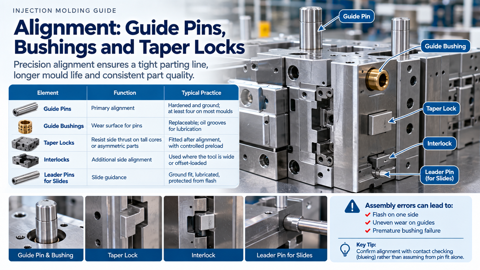
Alignment decides whether the parting line holds over time. Guide pins locate the halves; taper locks or interlocks take the side load from injection pressure.
| Element | Function | Typical practice |
|---|---|---|
| Guide pins | Primary alignment | Hardened and ground; at least four on most moulds |
| Guide bushings | Wear surface for pins | Replaceable; oil grooves for lubrication |
| Taper locks | Resist side thrust on tall cores or asymmetric parts | Fitted after alignment, with controlled preload |
| Interlocks | Additional side alignment | Used where the tool is wide or offset-loaded |
| Leader pins for slides | Slide guidance | Ground fit, lubricated, protected from flash |
Assembly errors here show up as flash on one side, uneven wear on guides, and premature bushing failure. Alignment should be confirmed with contact checking (blueing) rather than assumed from pin fit alone. Wear plates and guide components are only as good as the steel behind them, which we cover in our guide to mould steel selection.
Fits and Clearances That Matter
| Component pair | Requirement | Note |
|---|---|---|
| Cavity insert to pocket | Light interference or transition fit | Should seat without distorting the insert |
| Core to core plate | Accurate location, seated | Core movement shows as wall thickness variation |
| Guide pin to bushing | Ground sliding fit | Tight enough to align, free enough to move |
| Ejector pin to hole | Sliding fit with minimal clearance | Too loose flashes, too tight seizes when hot |
| Ejector plate to guide | Parallel movement | Binding causes uneven ejection |
| Sprue bushing to A plate | Correct shoulder contact | Controls seat depth and prevents leakage |
| Shut-off faces | Contact under preload | No contact, no seal |
| Slide to guide | Sliding fit with wear plates | Wear plates protect the base |
Where a fit is measured in hundredths, assembly is where those hundredths are confirmed — and where they are lost if components are mixed up or fitted without measurement. Fits should be selected against the ISO fits and limits system rather than by rule of thumb.
Ejection System Assembly
Ejection problems usually originate in assembly, not in the part design.
- Ejector plate parallelism — an unparallel plate loads some pins more than others, causing marks, bent pins and sticking parts.
- Pin length matching — pins should contact the part together. Unequal pin lengths produce local stress marks and, in some cases, cracks.
- Return springs — sized so the plate returns fully before the mould closes, with enough force for the coldest expected cycle.
- Guided ejection — for thin parts or close-tolerance pins, guided ejector plates prevent deflection.
- Clearance and flash — pin-to-hole clearance must let the pin move when hot but not let melt flash into the gap.
- Lubrication — an appropriate high-temperature lubricant, and no lubricant where it can contaminate the melt or the part surface.
A useful assembly check: move the ejector plate by hand through its full stroke before the mould is closed on the press. If it requires force, the cause is in the assembly, not in the process.
Cooling Circuit Assembly
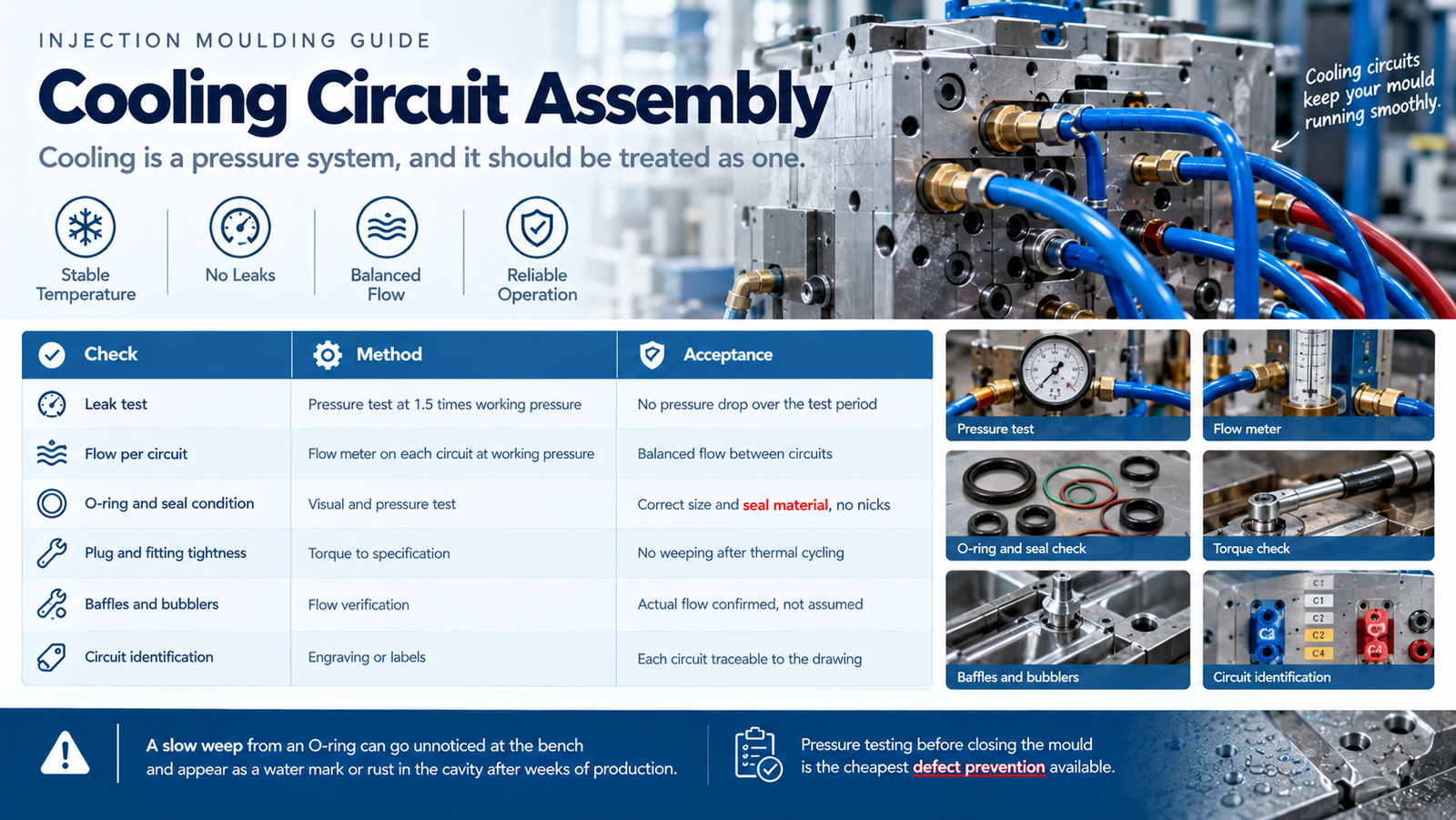
Cooling is a pressure system, and it should be treated as one.
| Check | Method | Acceptance |
|---|---|---|
| Leak test | Pressure test at 1.5 times working pressure | No pressure drop over the test period |
| Flow per circuit | Flow meter on each circuit at working pressure | Balanced flow between circuits |
| O-ring and seal condition | Visual and pressure test | Correct size and seal material, no nicks |
| Plug and fitting tightness | Torque to specification | No weeping after thermal cycling |
| Baffles and bubblers | Flow verification | Actual flow confirmed, not assumed |
| Circuit identification | Engraving or labels | Each circuit traceable to the drawing |
A slow weep from an O-ring can go unnoticed at the bench and appear as a water mark or rust in the cavity after weeks of production. Pressure testing before closing the mould is the cheapest defect prevention available.
Parting Line and Shut-off Contact
The parting line is the mould's seal. Contact should be verified, not assumed from the appearance of the faces.
- Check contact with blueing or shim stock at the shut-off surfaces and around the cavity
- Confirm the shut-off angle or step on the core matches the cavity
- Allow breathing space for air venting — full contact everywhere prevents venting and causes burns
- Verify that inserts do not sit proud of their pockets, which opens a flash gap on the parting line
- Confirm that supports and pillars sit at the correct height so injection pressure does not deflect the plates
The balance between contact and venting is deliberate. A mould that is "clamped tight everywhere" will trap gas; a mould with insufficient contact will flash. Draft is what lets the part release once that seal is broken — see our guide to draft angles in injection moulded parts.
Hot Runner and Feed System Assembly
Hot runner assembly adds thermal behaviour to mechanical alignment.
- Thermal expansion must be allowed for: the manifold grows when hot, and the assembly must not preload it cold
- Nozzle-to-gate alignment must be correct at operating temperature, not room temperature
- Thermocouples and heaters should be wired, labelled and checked for correct zone mapping
- Insulation and air gaps must be maintained so the manifold does not lose heat to the plates
- Manifold support should allow expansion without losing sealing force
Errors here appear as gate freezing, drooling, cold slugs in the part, or a manifold leak that runs plastic onto the plate faces.
Pre-Delivery Checks Before the Mould Ships
| Check | Purpose |
|---|---|
| Full close and open cycle at low pressure | Verifies alignment, slide timing, safe return |
| Dry cycle on the press | Confirms ejection and plate motion under machine conditions |
| Cooling leak and flow test | Confirms the sealing system holds at pressure |
| Safety checks on slides and cylinders (machinery safety practice) | No interference or crush points |
| Water and electrical connections labelled | Correct connection at the customer press |
| Spare parts, drawings and reports provided | Maintainability |
| T1 trial and dimensional first article | Confirms the mould produces the specified part |
A mould that arrives without documentation is a mould whose assembly cannot be assessed later. Records of fits, clearances, circuit layouts and trial results are part of the deliverable. The dimensional verification behind those reports follows the same discipline as our in-house quality control process.
Common Assembly Problems and Their Causes
| Problem | Likely cause |
|---|---|
| Flash appearing after some production | Insufficient shut-off contact, worn guides, or plate deflection |
| Part sticking on one side | Alignment biased, ejector pins uneven, or inadequate draft locally |
| Water marks in the cavity | Weeping O-ring or fitting not pressure tested |
| Uneven ejection marks | Ejector plate not parallel or pin lengths unequal |
| Slide timing faults | Assembled without dry cycling, or stroke set at the bench rather than on the press |
| Bushing wear within months | Misalignment during assembly or inadequate lubrication |
| Manifold leak or cold gates | Thermal expansion not allowed for, thermocouples mapped wrongly |
| Wall thickness variation | Core not seated or pocket fit causing insert shift |
Most of these are found by a systematic pre-delivery check and not by trial and error on the customer's press.
Conclusion
Mould assembly is the stage where good machining becomes a good tool. Verify components before assembly, follow a sequence that starts with flatness and alignment, confirm fits by measurement and contact checking rather than by feel, pressure test the cooling system, dry cycle the moving elements, and document the result.
A mould assembled in this order will run for millions of shots with routine maintenance. A mould assembled quickly to meet a deadline will spend the first weeks of production being corrected — on the customer's machine, with the customer watching.
With in-house mould design, machining, assembly and trial, we control the whole chain from drawing to first article as part of our custom injection moulding services, and deliver each mould with the fit, test and trial records that support it. Send us your part drawing to discuss tooling design, assembly standards and the trial documentation you need.
FAQ
What is mould assembly in plastic injection moulding?
Mould assembly is the process of building the mould from its machined components: fitting cavity and core inserts, installing guide pins and bushings, assembling the ejection system, pressure testing the cooling circuits, fitting slides and hot runner components, and verifying that the closed mould aligns, seals and cycles correctly.
Why does alignment matter so much in mould assembly?
Alignment controls the parting line seal and the position of the core relative to the cavity. Misalignment causes flash on one side, uneven wall thickness, premature guide bushing wear and shortened mould life. It is confirmed by contact checking, not assumed from pin fit.
How should cooling circuits be tested during assembly?
Each circuit should be pressure tested at about 1.5 times the working pressure and flow-verified with a flow meter. O-rings, plugs and fittings should be checked at operating temperature where possible. A slow leak that is invisible at the bench causes water marks and corrosion once the mould is in production.
What is checked before a mould is delivered?
Low-pressure opening and closing checks, a dry cycle on the press, cooling leak and flow tests, slide and cylinder safety checks, labelling of water and electrical connections, and a T1 trial with dimensional first article inspection. Documentation of fits, circuits and trial results should ship with the mould.
What causes uneven ejection in a new mould?
The most common causes are an ejector plate that is not parallel, ejector pins of unequal length, insufficient guiding on thin parts, or binding from a misaligned ejector plate guide. These are assembly faults rather than process faults and are resolved in the tool.
What causes a manifold leak in a hot runner?
Usually thermal expansion that was not allowed for: the manifold grows when hot and either loses sealing force or overloads its supports. Incorrect nozzle-to-gate alignment and wrong thermocouple zone mapping cause the related symptoms of cold gates and drooling.