Mold etching — also called texturing or graining — is the step that turns a plain polished cavity into a leather grain, a matte finish, a geometric pattern or a hidden logo. It is also the step that most often goes wrong after the tool is already cut, because etching is irreversible: you can take material off a mould, you cannot put it back.
This guide covers the four texturing methods, how depth is controlled, the draft angle rules that decide whether the part releases, and the design checks that prevent a tool from being re-cut.
What etching does and why it matters
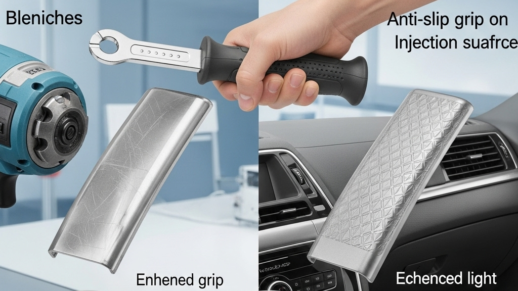
A textured surface changes more than appearance:
It hides defects. A fine grain conceals flow marks, weld lines and minor sink that would be obvious on a polished surface. This is why textured parts tolerate wider process windows.
It changes how the part releases. Every 0.025 mm of etch depth adds friction on ejection. A texture that looks harmless on a drawing can transform a part that drops out of the tool into one that needs a release agent.
It changes the cost. Texturing adds 5 to 15 percent to tool cost and, in deep textures, adds cycle time because a textured surface cools differently and ejects more slowly.
It cannot be undone. Polishing a textured cavity removes texture depth and changes the part dimension. There is no additive process that rebuilds it — a mis-etched tool is a welding and re-cutting job.
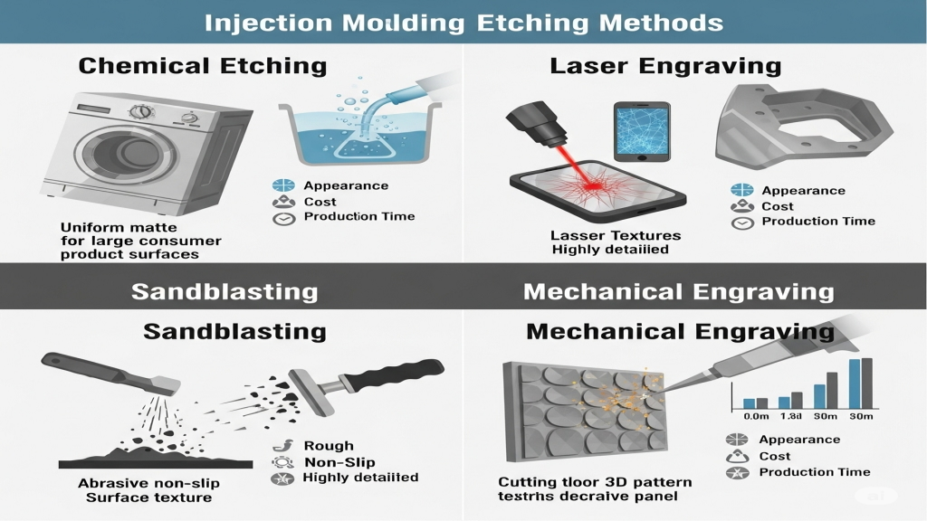
The four texturing methods
| Method | Depth range | Pattern control | Best for |
|---|---|---|---|
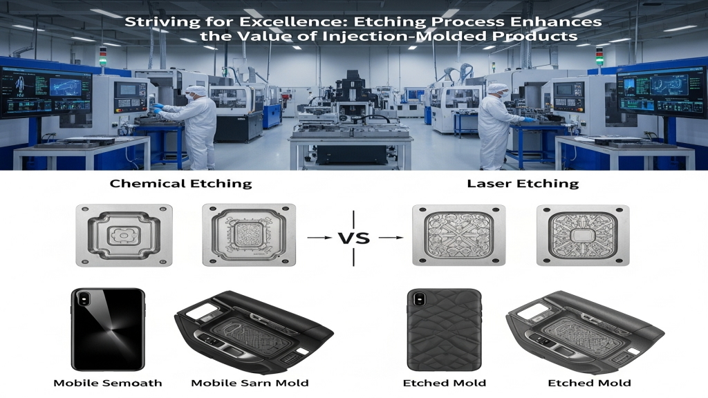
| Chemical etching | 0.01 – 0.20 mm | Excellent — photo-resist mask | Leather grains, geometric patterns, logos |
| Sandblasting | 0.005 – 0.05 mm | Coarse — grit size only | Uniform matte, non-directional |
| Laser texturing | 0.01 – 0.50 mm | Excellent — direct digital | Fine detail, deep 3D patterns, repairs |
| EDM texturing | 0.01 – 0.10 mm | Good — electrode pattern | Hardened steels, intricate detail |
Chemical etching dominates because it is repeatable across cavities and produces the standard Mold-Tech (MT) grain library that every moulder and every customer recognises. The MT number on a drawing is a specification: MT-11010 is a fine matte, MT-11020 and MT-11030 are progressively coarser, and the deeper series produce heavy leather and stipple patterns.
| MT grain | Approximate depth | Typical application |
|---|---|---|
| MT-11000 series (fine) | 0.01 – 0.03 mm | Matte housings, appliance panels |
| MT-11010 | 0.013 mm | Fine matte, most common |
| MT-11020 | 0.025 mm | Medium matte |
| MT-11030 | 0.038 mm | Coarse matte, hides flow marks |
| MT-11200 series | 0.05 – 0.10 mm | Leather grain, automotive interior |
| MT-11500 series | 0.10 – 0.20 mm | Heavy texture, deep grip patterns |
How chemical etching works
| Step | What happens | Control point |
|---|---|---|
| Cleaning | Cavity degreased and de-scaled | Any residue causes uneven etch |
| Resist application | Photo-sensitive film applied to the cavity | Film thickness sets minimum feature size |
| Exposure | Film exposed through a printed pattern | Pattern alignment to the cavity |
| Development | Unexposed resist washed away | Feature edges and depth uniformity |
| Etching | Acid or ferric chloride attacks exposed steel | Bath chemistry, temperature, dwell time |
| Resist removal | Remaining film stripped | Residual film contaminates the next step |
| Inspection | Depth measured, pattern checked | Depth gauge plus visual against master |
The depth is controlled by bath chemistry, temperature and time. A 1 °C change in bath temperature or a 10 percent change in concentration moves the depth by several microns, which is why etching is done by specialists with calibrated baths and not in-house.
The draft angle rule that decides success
This is the number that matters most in design:
| Etch depth | Added draft per side | Total draft recommendation |
|---|---|---|
| 0.013 mm (fine matte) | 0.5° | 1.5° |
| 0.025 mm | 1.0° | 2.0° |
| 0.038 mm | 1.5° | 2.5° |
| 0.075 mm | 3.0° | 4.0° |
| 0.150 mm | 6.0° | 7.0° |
The rule of thumb used across the industry is one degree of extra draft for every 0.025 mm of etch depth, on top of the 1° minimum that an untextured wall needs. A part designed with 1° draft and then textured to MT-11030 will drag, scuff and crack at ejection — and the fix is a tool modification, not a process setting.
Our article on the role of draft angles covers the base requirement, and demolding scratches in ABS parts is the defect that results when the drafting is wrong.
Design rules for textured parts
| Rule | Value | Why |
|---|---|---|
| Minimum draft | 1.5° for fine texture, 3° for heavy | Release without scuffing |
| Wall thickness | 2.0 mm minimum under heavy texture | Texture reduces effective wall |
| Parting line | Place in a non-visible area | Texture hides the mismatch |
| Corners | Radius 1.0 mm minimum | Sharp corners etch unevenly |
| Text and logos | 0.4 mm minimum stroke width | Thinner strokes fill with resist |
| Gate position | Away from textured cosmetic faces | Gate blush is hard to polish out |
| Ejector placement | On the untextured side where possible | Ejector marks are more visible on texture |
| Texture boundary | Define a hard line or a fade | Partial textures need a mask edge |
Textures and gloss are two different specifications, and they interact. A high-gloss part has no texture at all; a matte part has shallow texture. Our article on spray-free high-gloss PMMA covers the opposite end of that spectrum, and mould texture points needing attention covers the production side.
What etching does to weld lines and defects
A textured surface is the cheapest way to hide a weld line. A deep grain breaks up the visual discontinuity that a polished surface would show clearly.
| Defect | On polished surface | On textured surface |
|---|---|---|
| Weld line | Clearly visible | Hidden below MT-11020 |
| Flow marks | Visible | Hidden below MT-11030 |
| Minor sink | Visible under gloss | Partly hidden |
| Gate blush | Visible | Less visible |
| Ejector marks | Visible | More visible — texture highlights them |
| Scratches in service | Very visible | Hidden |
The trade-off is that texture conceals process problems during development, and they can reappear when a different batch of material runs. Our article on how mould etching affects weld line strength covers the mechanical side — hiding a weld line visually does not restore its strength.
Maintenance and repair
| Situation | What happens | Options |
|---|---|---|
| Texture worn in high-wear areas | Gloss returns locally | Re-etch the whole cavity |
| Tool damage in a textured area | Local polished spot | Laser touch-up or weld and re-etch |
| Texture depth drifting | Part gloss changes over production | Measure gloss on a master, re-etch when out |
| Deep texture with poor release | Scuffing, white marks | Increase draft — tool modification |
| Partial texture repair | Visible boundary | Full re-etch usually cheaper |
The maintenance rule is to keep a textured master sample, signed by the customer, and measure gloss against it on a schedule. Texture wear is gradual and invisible day to day; the master sample is the only objective reference.
Our general injection moulding defects guide covers the surface defects that texture can hide or create, the cost effects of geometry are in concave versus convex design, and the material side is in our injection moulding materials overview.
Surface and tooling data in this guide follows the test methods published by ASTM International and ISO, with typical values cross-checked against MatWeb and Engineering Toolbox. Tooling and texturing practice reflects Plastics Technology guidance and PLASTICS industry standards, with material characterisation maintained through SPE and NIST reference data. For the surface-chemistry context, see chemical milling.
What is mold etching?
Mold etching is the chemical or laser process that cuts a pattern into a mould cavity, producing a textured surface on the moulded part. Chemical etching uses a photo-resist mask and an acid bath; laser texturing cuts the pattern directly.
How deep should a texture be?
It depends on the effect. Fine matte is 0.01 to 0.03 mm, medium matte 0.025 to 0.04 mm, leather grain 0.05 to 0.10 mm, and heavy grip texture 0.10 to 0.20 mm. Depth is specified by MT grain number on the drawing.
How much draft angle do I need for a textured part?
One degree of extra draft for every 0.025 mm of etch depth, on top of the 1° minimum. A part textured to 0.038 mm needs about 2.5° total draft; a 0.15 mm texture needs about 7°.
Can a texture be removed if the customer changes their mind?
Only by polishing, which removes depth and changes the part dimension. A polished cavity can be re-etched to a different pattern, but the wall thickness will have changed. Decide the texture before the tool is cut.
Does texturing hide weld lines?
Visually yes, from MT-11020 upward. Mechanically no — the weld line is still the weakest plane in the part. If the part has to carry load across a weld line, the gate position has to be fixed, not hidden.
Why does my textured part scuff or crack at ejection?
Almost always insufficient draft. Texture adds friction, and a wall drafted for a polished cavity will drag once it is etched. The fix is a tool modification to add draft, or a reduction in texture depth.
Conclusion
Etching is a design decision disguised as a finishing step. The texture number on the drawing sets the draft angle, the ejection force, the cycle time, the gloss tolerance and whether the tool can ever be corrected. Specify MT grain and draft together, keep a signed master sample, and treat texture wear as a measurable production variable rather than a visual impression.
At Rui Cheng we handle mould texturing through qualified etching partners, with in-house tooling, ±0.02 mm tolerance capability, MT grain verification and ISO 9001 / IATF 16949 processes. Send us the drawing with the texture requirement and the cosmetic surfaces marked, and we will come back with a tooling cost, a draft angle review and an indicative part cost.