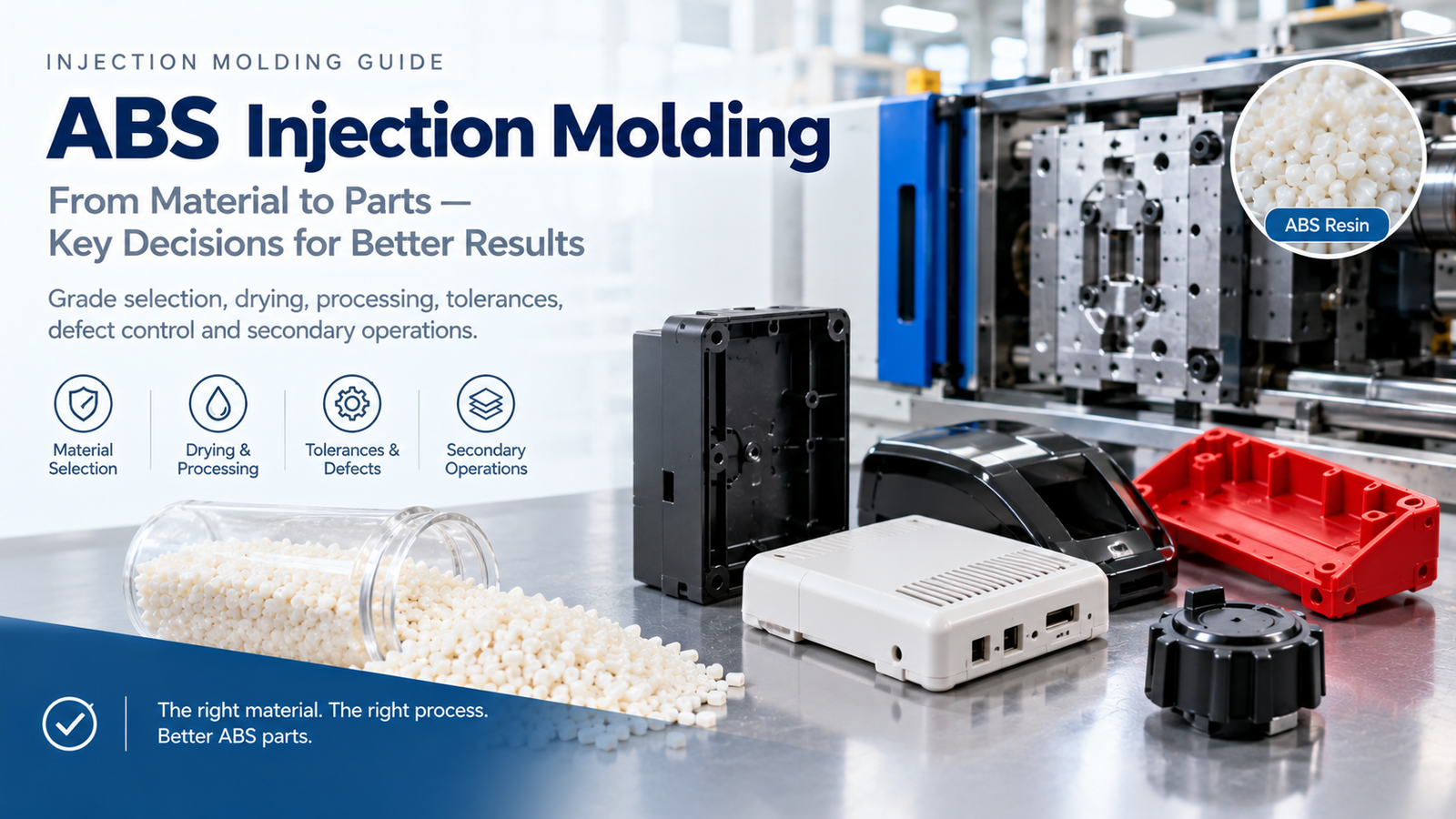
Electronics is the most demanding segment in injection moulding. A part that would be perfectly acceptable in a furniture application is scrap in a consumer device: the tolerance is tighter, the cosmetic standard is higher, the material must pass a flammability test, and static discharge can destroy the very components the housing protects. Electronics injection moulding is therefore less about the press and more about controlling material, tolerance and consistency together.
This guide covers what electronics moulding requires, how materials are selected, how ESD and flammability are handled, and what to specify on a drawing.
What Makes Electronics Moulding Different
| Requirement | Typical specification |
|---|---|
| Flammability | UL 94 V-0 at the wall thickness used, often 1.5 mm or thinner |
| Glow wire | GWIT / GWFI for appliance standards |
| Tracking resistance | Comparative tracking index (CTI) 600 V for many connectors |
| Electrical strength | Dielectric strength verified for the wall and creepage path |
| Static control | Antistatic, dissipative or conductive grades depending on the product |
| Dimensional tolerance | Plus/minus 0.05 mm general, 0.02 mm on critical features |
| Flatness | Coplanarity specified on covers and connectors |
| Cosmetic | Defined appearance, texture and colour, often with no visible gate marks |
| Traceability | Material lots and production batches recorded |
The complication is that these requirements pull in different directions. Flame retardant additives usually reduce impact strength and increase warpage. Thin walls improve heat dissipation but raise filling pressure. Antistatic grades add fillers that change shrinkage. Getting all of them right at once is the engineering problem.
Materials Used in Electronics Injection Moulding
| Material | Flammability | Notable strengths | Typical use |
|---|---|---|---|
| ABS | Typically V-0 in FR grades | Easy processing, good surface, low cost | Housings, covers, cosmetic parts |
| PC | V-0 to V-2 depending on grade | Impact strength, transparency options | Housings with impact or heat needs |
| PC/ABS | V-0 in FR grades | Balance of toughness, heat and processing | Laptop and appliance enclosures |
| PBT | V-0 | Dimensional stability, low moisture, CTI | Connectors, sockets, bobbins |
| PA66 | V-0 in FR grades | Mechanical strength, heat resistance | Structural parts, brackets |
| PBT-GF30 / PA-GF30 | V-0 | Stiffness, creep resistance | Connector bodies, supports |
| PPS | Inherently V-0 | Heat and chemical resistance, low shrinkage | SMD parts, high-temperature connectors |
| PEEK | Inherently V-0 | Highest performance, very high cost | Specialised semiconductor and medical parts |
Material choice is usually driven by three things: the flammability standard the product must meet, the temperature the part sees in service, and whether the part carries mains voltage. A connector body holding live terminals is a PBT, PA or PPS decision, not an ABS decision.
Reference properties for the grades under consideration should always be checked against the supplier resin data rather than a generic table.
Flame Retardancy: What UL 94 Actually Requires
| Rating | Behaviour | Practical meaning |
|---|---|---|
| V-0 | Self-extinguishing in under 10 seconds, no burning drips | The standard for enclosed electronics |
| V-1 | Self-extinguishing in under 30 seconds, no burning drips | Lower requirement |
| V-2 | Self-extinguishing, burning drips permitted | Not acceptable near live parts |
| 5VA / 5VB | Very high resistance to flame and burning drips | Enclosure standards |
Two points are commonly missed. First, the rating applies at a specific wall thickness, so a V-0 grade at 3 mm may not be V-0 at 1.2 mm. Second, flame retardant additives increase melt viscosity and shrink differently from the base resin, so the tooling shrinkage must use the FR grade data, not the unfilled data.
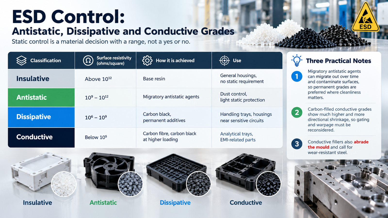
ESD Control: Antistatic, Dissipative and Conductive Grades
Static control is a material decision with a range, not a yes or no.
| Classification | Surface resistivity (ohms/square) | How it is achieved | Use |
|---|---|---|---|
| Insulative | Above 10 to the 12 | Base resin | General housings, no static requirement |
| Antistatic | 10 to the 9 to 10 to the 12 | Migratory antistatic agents | Dust control, light static protection |
| Dissipative | 10 to the 6 to 10 to the 9 | Carbon black, permanent additives | Handling trays, housings near sensitive circuits |
| Conductive | Below 10 to the 5 | Carbon fibre, carbon black at higher loading | Analytical trays, EMI-related parts |
Three practical notes. Migratory antistatic agents can migrate out over time and contaminate surfaces, so permanent grades are preferred where cleanliness matters. Carbon-filled conductive grades show much higher and more directional shrinkage, so gating and warpage must be reconsidered. Conductive fillers also abrade the mould and call for wear-resistant steel.
Tolerances, Flatness and Fit
Electronic assemblies are unforgiving about dimensions because parts often connect to each other, not to a flexible surface.
| Feature | Typical tolerance | Note |
|---|---|---|
| General dimensions | Plus/minus 0.05 mm | Confirm against drawing callouts |
| Critical fit features | Plus/minus 0.02 mm | Where a connector or lens must align |
| Coplanarity on covers | 0.15 – 0.3 mm across the part | Drives flatness control and warpage |
| Boss positions | Plus/minus 0.05 mm | Screw alignment |
| Snap fit engagement | 0.1 – 0.2 mm | Function of design, not just process |
Achieving 0.02 mm features reliably means the process, not just the drawing, has to be controlled: stable melt temperature, consistent hold profile and balanced cooling. Where tolerance is critical, tolerance analysis should be checked against ISO dimensional practice before tooling is cut, and confirmed by dimensional verification on first article with a documented report.
Insert Moulding and Overmoulding for Terminals
Many electronic parts combine metal and plastic in one shot.
- Insert moulding places stamped terminals, busbars or metal frames in the tool before injection. The key controls are insert location (position pins), insert preheating, and prevention of flash around the metal.
- Overmoulding moulds plastic over a pre-formed part, including cables and connectors. Adhesion between the two materials decides whether the part stays sealed.
- Metal insert pull strength should be specified on the drawing and verified on first article, because it depends on knurl geometry as much as on the resin.
EMI Considerations
Where a part must attenuate electromagnetic interference, the options are material and process based: conductive fillers inside the resin, conductive coatings applied after moulding, metal shielding cans assembled into the part, or plated plastic. Conductive filling rarely gives enough attenuation on its own for strict requirements, so shielding is often a post-moulding operation that must be planned at the design stage.
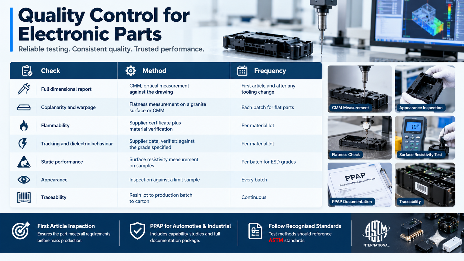
Quality Control for Electronic Parts
| Check | Method | Frequency |
|---|---|---|
| Full dimensional report | CMM, optical measurement against the drawing | First article and after any tooling change |
| Coplanarity and warpage | Flatness measurement on a granite surface or CMM | Each batch for flat parts |
| Flammability | Supplier certificate plus material verification | Per material lot |
| Tracking and dielectric behaviour | Supplier data, verified against the grade specified | Per material lot |
| Static performance | Surface resistivity measurement on samples | Per batch for ESD grades |
| Appearance | Inspection against a limit sample | Every batch |
| Traceability | Resin lot to production batch to carton | Continuous |
A first article inspection and, for automotive and industrial customers, a PPAP-style documentation package with capability studies is the baseline expectation. Dimensional claims without measurement records are opinions, and electronics customers know the difference. Test methods for these properties should reference recognised ASTM standards.
Common Defects and Their Causes
| Defect | Likely cause | Fix |
|---|---|---|
| Silver streaks on PBT or PA parts | Wet resin — hydrolysing at melt temperature | Dry to the grade specification and monitor dew point |
| Warpage on flat covers | Uneven cooling, fibre orientation, or FR filler effects | Balance cooling, review gating, confirm shrinkage with the actual grade |
| Short shots on thin walls | Wall too thin for the flow length, low melt temperature | Increase melt temperature and speed, review wall thickness against flow length |
| Weld lines at connector ribs | Flow fronts meeting around a hole or insert | Reposition the gate, raise temperatures, add venting at the weld location |
| Sink marks opposite bosses | Boss wall too thick | Core the boss, reduce boss wall to about 60 percent of nominal wall |
| Flash on insert parts | Insert fit clearance too large, insufficient clamp | Tighten insert fits, verify clamp tonnage |
| Cosmetic gate marks on visible surfaces | Gate position chosen for filling only | Move the gate to a hidden face or use a different gate type |
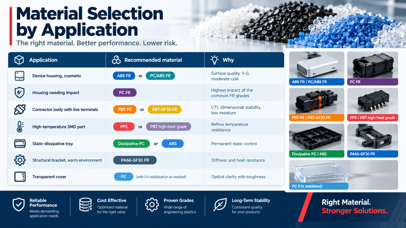
Material Selection by Application
| Application | Recommended material | Why |
|---|---|---|
| Device housing, cosmetic | ABS FR or PC/ABS FR | Surface quality, V-0, moderate cost |
| Housing needing impact | PC FR | Highest impact of the common FR grades |
| Connector body with live terminals | PBT FR or PBT-GF30 FR | CTI, dimensional stability, low moisture |
| High-temperature SMD part | PPS or PBT high-heat grade | Reflow temperature resistance |
| Static-dissipative tray | Dissipative PC or ABS | Permanent static control |
| Structural bracket, warm environment | PA66-GF30 FR | Stiffness and heat resistance |
| Transparent cover | PC (with UV stabilisation as needed) | Optical clarity with toughness |
Conclusion
Electronics injection moulding is a specification problem before it is a processing problem. Flammability rating at the actual wall thickness, tracking resistance for live parts, static classification, coplanarity and the tolerance on mating features all have to be defined before the tool is cut — and the grade data used for shrinkage must come from the FR or filled grade, not the base resin.
Where those specifications are clear and the process is controlled, the parts are repeatable. Where they are assumed rather than stated, the failures appear at incoming inspection, which is the most expensive place to find them.
With in-house tooling, dimensional inspection and documented first article and in-process inspection, we support electronics programmes from design review through stable volume production. Send us your drawing and application details to discuss material selection, tolerances and the documentation package your project requires.
FAQ
What is electronics injection moulding?
Electronics injection moulding is the production of plastic parts for electronic devices — housings, connectors, bobbins, trays and internal components — where the requirements go beyond basic moulding: flammability ratings such as UL 94 V-0, tight tolerances, static control and documented traceability.
Which plastic is best for electronic housings?
ABS with flame retardant additives and PC/ABS blends are the most common choices for housings, offering V-0 performance, good surface finish and reasonable cost. Polycarbonate is preferred where impact strength is critical, and PBT or PPS where heat resistance or live terminals are involved.
What does UL 94 V-0 mean?
UL 94 V-0 means a vertical specimen self-extinguishes within 10 seconds without producing burning drips. The rating applies at a specific wall thickness, so a material rated V-0 at 3 mm may not meet V-0 at 1.2 mm. Always confirm the rating at the thickness used in the part.
What is a dissipative plastic?
A dissipative plastic has a surface resistivity between roughly 10 to the 6 and 10 to the 9 ohms per square, achieved with carbon black or permanent additives. It prevents static build-up near sensitive circuits without conducting current like a metal.
Can injection moulded parts provide EMI shielding?
Not by themselves in most cases. Conductive fillers in the resin give limited attenuation; effective shielding usually requires conductive coatings, plated plastic, or integrated metal shielding. This should be planned at the design stage rather than added after moulding.
What tolerances are realistic for electronic parts?
Plus/minus 0.05 mm is a realistic general tolerance for moulded electronic parts, with plus/minus 0.02 mm achievable on critical features when the process is tightly controlled and the part is measured with an appropriate instrument such as a CMM. Coplanarity is usually specified separately for flat parts.