Introduction
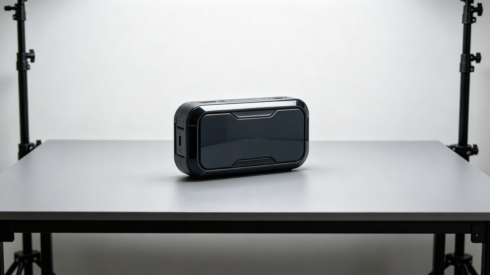
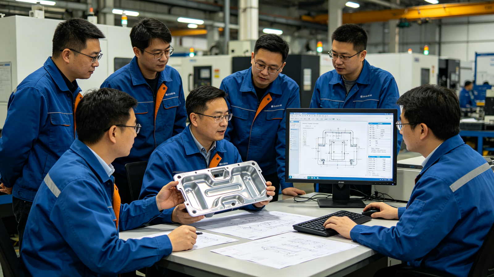
Glass‑filled thermoplastics are widely adopted across automotive, electrical and industrial hardware industries for enhanced mechanical performance. Manufacturers frequently select glass‑reinforced grades to boost tensile strength, rigidity and thermal stability of final molded components. The embedded glass fibers bring prominent abrasive risks to injection mold surfaces during mass‑volume production. Many project teams overlook tooling degradation risk at early design phase and face unexpected mold failure in serial production.
Mold life directly determines overall project cost, delivery stability and part dimensional consistency for high‑volume molding programs. Even well‑built molds will suffer progressive material loss under continuous scouring from hard glass‑fiber particles. Glass‑fiber content, processing parameters and tool steel grade jointly define the actual service cycles of injection molds. Operators need to balance component performance targets and long‑term tooling maintenance expenditure.
What Wear Mechanisms Does Glass‑Filled Plastic Trigger on Injection Molds?
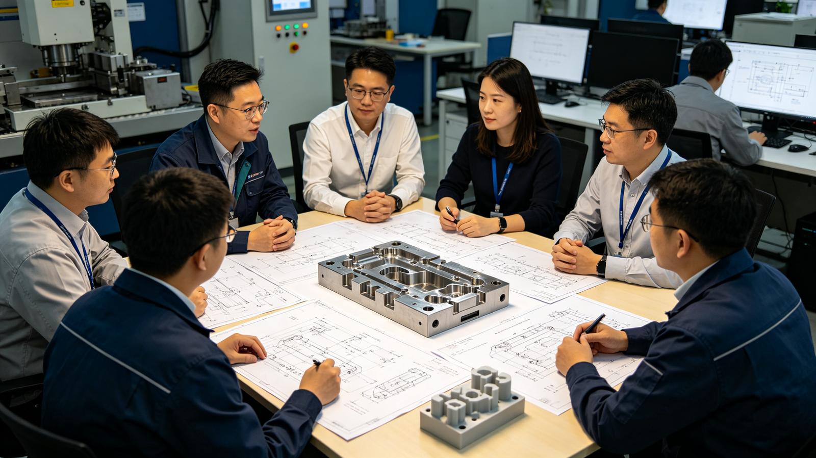
During each injection shot, molten glass‑filled resin flows through gate and runner channels, and hard glass fibers continuously scrape against mold steel substrate under high injection pressure. Abrasive erosion represents the dominant failure mechanism for molds running glass‑filled polymers. Localized high‑velocity melt flow concentrates fiber impact stress on specific mold zones, and cumulative micro‑scratches evolve into visible surface damage after thousands of production cycles. Secondary thermal‑fatigue effects also accelerate material degradation when processing temperature keeps fluctuating in repeated molding loops.
Abrasive scraping: Hard glass fibers act like micro‑abrasives and strip tiny steel fragments from cavity and runner surfaces in every injection cycle.
Local flow‑velocity erosion: High‑speed melt at gate positions amplifies fiber impact force and speeds up gate insert wear significantly.
Thermal‑cycle fatigue: Alternating heating and cooling cycles generate micro‑cracks on mold surface, cooperating with abrasion to expand surface defects.
Parting‑line galling: Glass‑filled flash squeezes across shut‑off surfaces and gradually erodes sealing edges, causing worsening flash issues.
⚠️ Glass‑filled plastics mainly induce abrasive wear concentrated on gate, sharp corner and parting‑line regions of injection molds.
Which Mold Zones Suffer the Most Severe Damage from Glass‑Filled Resins?
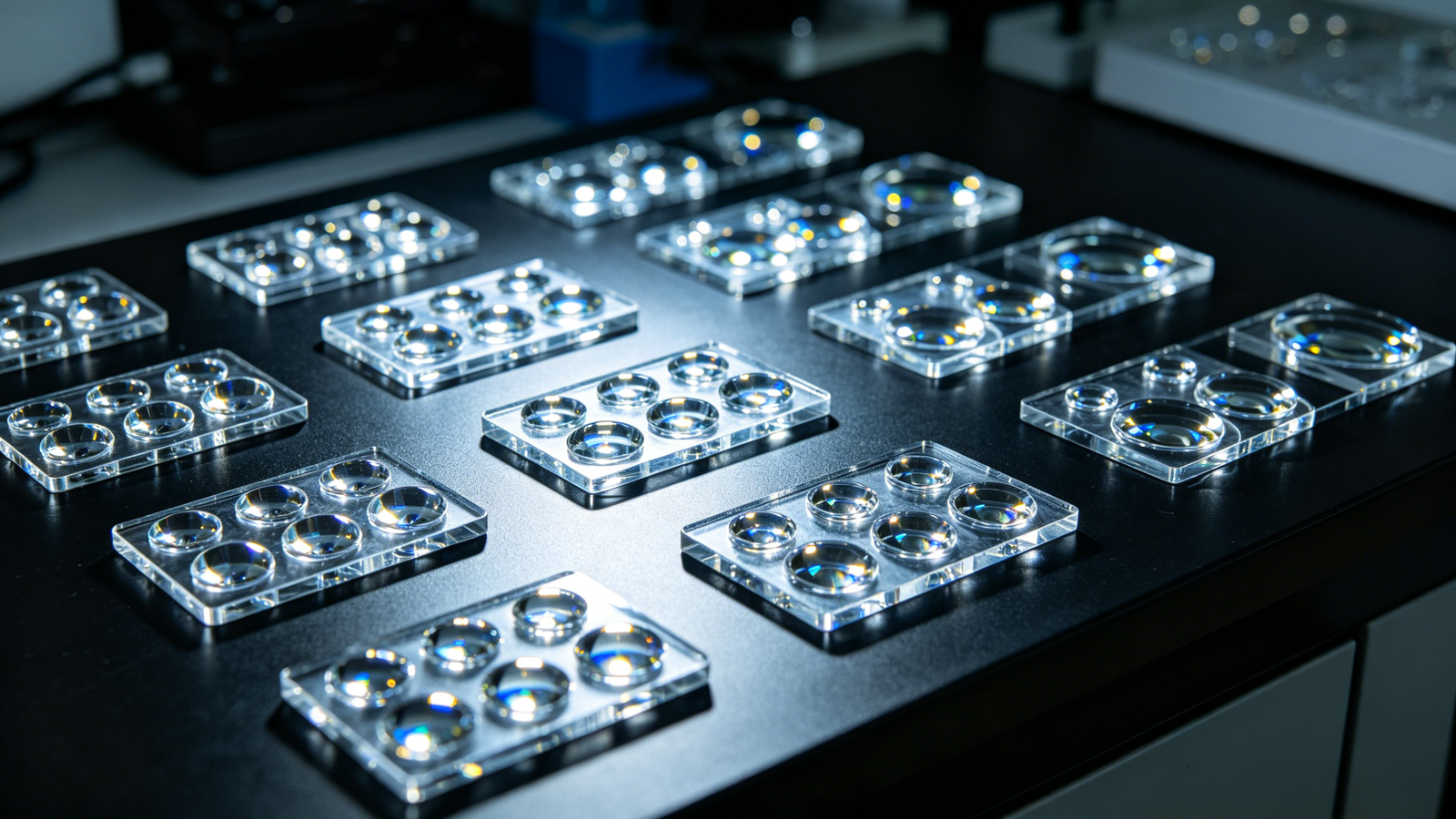
Different structural positions of injection molds bear uneven impact from flowing glass‑filled resin, and high‑flow‑speed areas always receive the heaviest abrasive attack. Gate areas encounter maximum melt velocity when molten polymer enters mold cavity, so fiber‑driven erosion emerges earliest in this region. Sharp inner corners change melt flow direction and force glass fibers to collide with steel surfaces, leaving linear scratch traces on cavity walls. Parting‑line shut‑off faces keep contacting resin flash containing glass particles, which slowly wears down sealing land and raises flashing risk for finished parts.
Gate area: This zone endures the highest melt velocity; replaceable hardened inserts are strongly recommended for glass‑filled material molding.
Sharp inner corners: Flow deflection forces glass fibers to strike steel surfaces, generating directional scratch marks on cavity surfaces.
Parting‑line shut‑off surfaces: Repeated extrusion of glass‑filled flash gradually wears sealing edges and deteriorates part‑sealing performance.
Thin rib‑and‑groove features: Narrow flow gaps increase local shear rate and accelerate abrasive loss on small‑size mold cores.
🔍 Gate, sharp corners and parting‑line sealing surfaces are the highest‑wear zones for molds processing glass‑filled plastics.
How to Quantify Mold‑Life Reduction Caused by Different Glass‑Fiber Contents?

Higher glass‑fiber weight percentage inside polymer matrix brings stronger abrasive property and shortens achievable mold cycle counts. Unfilled engineering plastics serve as baseline reference for relative wear assessment. Every 10% increase of glass‑fiber loading will obviously elevate abrasive aggression toward mold steel. Identical mold tool will deliver greatly different service life when switching from non‑filled resin to 30 %‑40 % glass‑filled grades. Practical production statistics reflect obvious gap between theoretical mold rating and real‑world shot capacity under abrasive processing conditions.
10 %‑15 % glass‑fiber loading: Moderate abrasion risk; well‑hardened P20 steel can satisfy medium‑volume production requirements.
20 %‑30 % glass‑fiber loading: High‑abrasion scenario; standard pre‑hardened P20 will fail prematurely; H13 or equivalent hardened tool steel becomes necessary.
40 %‑50 % glass‑fiber loading: Extreme‑wear condition; powder‑metallurgy steel plus PVD hard coating and replaceable inserts are required for stable long‑run production.
Unfilled reference grade: Zero glass‑fiber content delivers baseline mold‑cycle performance for cross‑material comparison.
📊 Raising glass‑fiber proportion inside plastic compound directly reduces the total achievable service cycles of injection molds.
Comparison of Tool Steel Performance for Glass‑Filled Plastic Molding
| Tool Steel Grade | Hardness Range | Relative Abrasion Resistance | Recommended Glass‑Fiber Limit | Typical Achievable Cycles |
|---|---|---|---|---|
| P20 | 28‑32 HRC | Low | <15 % GF | 50 000‑120 000 |
| H13 Hardened | 48‑52 HRC | High | ≤30 % GF | 300 000‑600 000 |
| S136‑H | 48‑52 HRC | Medium‑High | ≤25 % GF | 200 000‑450 000 |
| Powder‑Metallurgy Steel | 54‑60 HRC | Very High | Up to 50 % GF | 500 000‑1 000 000+ |
If you need professional tool‑steel suggestion customized for your glass‑filled molding project, please contact us.
Practical Strategies to Preserve Injection Mold Life for Glass‑Filled Molding
Glass‑filled material projects can achieve greatly extended tool service life by combining proper steel selection, surface treatment, mold‑structure optimization and reasonable process tuning. Reasonable mold design and surface hardening treatments can offset most abrasive damage induced by glass‑fiber fillers. Even high‑glass‑content applications can obtain stable long‑term output without frequent mold repairing. Process parameters also need fine‑tuning to reduce melt‑flow shear and fiber‑impact intensity inside mold cavities.
1.Tool‑steel selection: Select H13 hardened or powder‑metallurgy steel for molds running glass‑filled resins above 20 % fiber content.
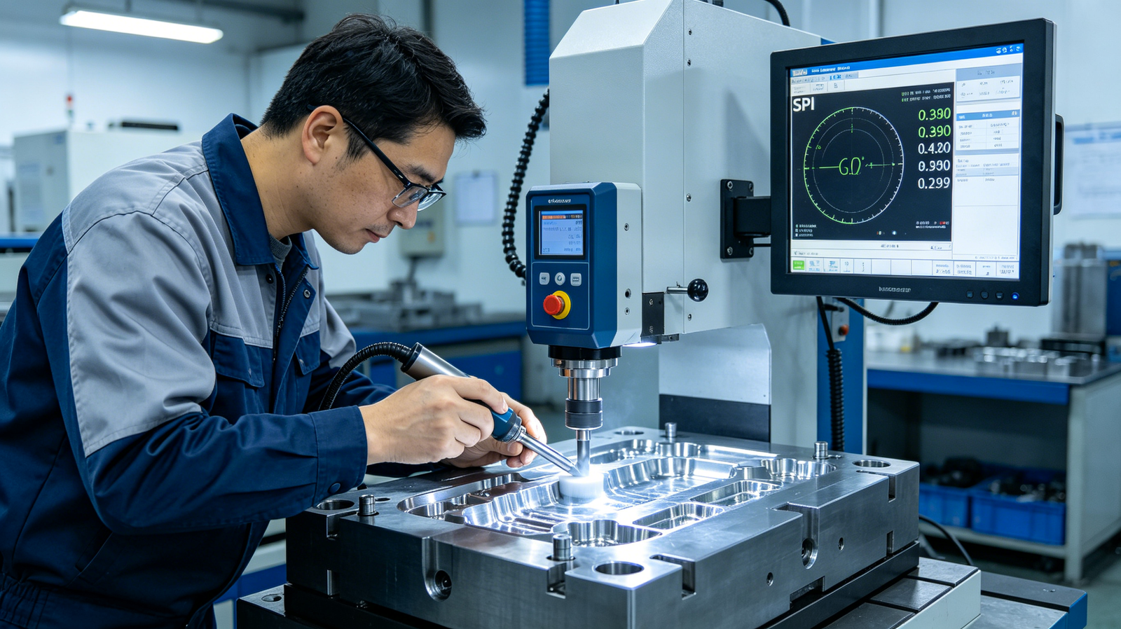
2.Surface hardening treatment: Apply nitriding plus CrN / AlTiN PVD coating to high‑wear mold surfaces including gates and runners.
3.Mold‑structure optimization: Adopt replaceable gate inserts and increase radius for sharp inner corners to mitigate fiber‑impact erosion.
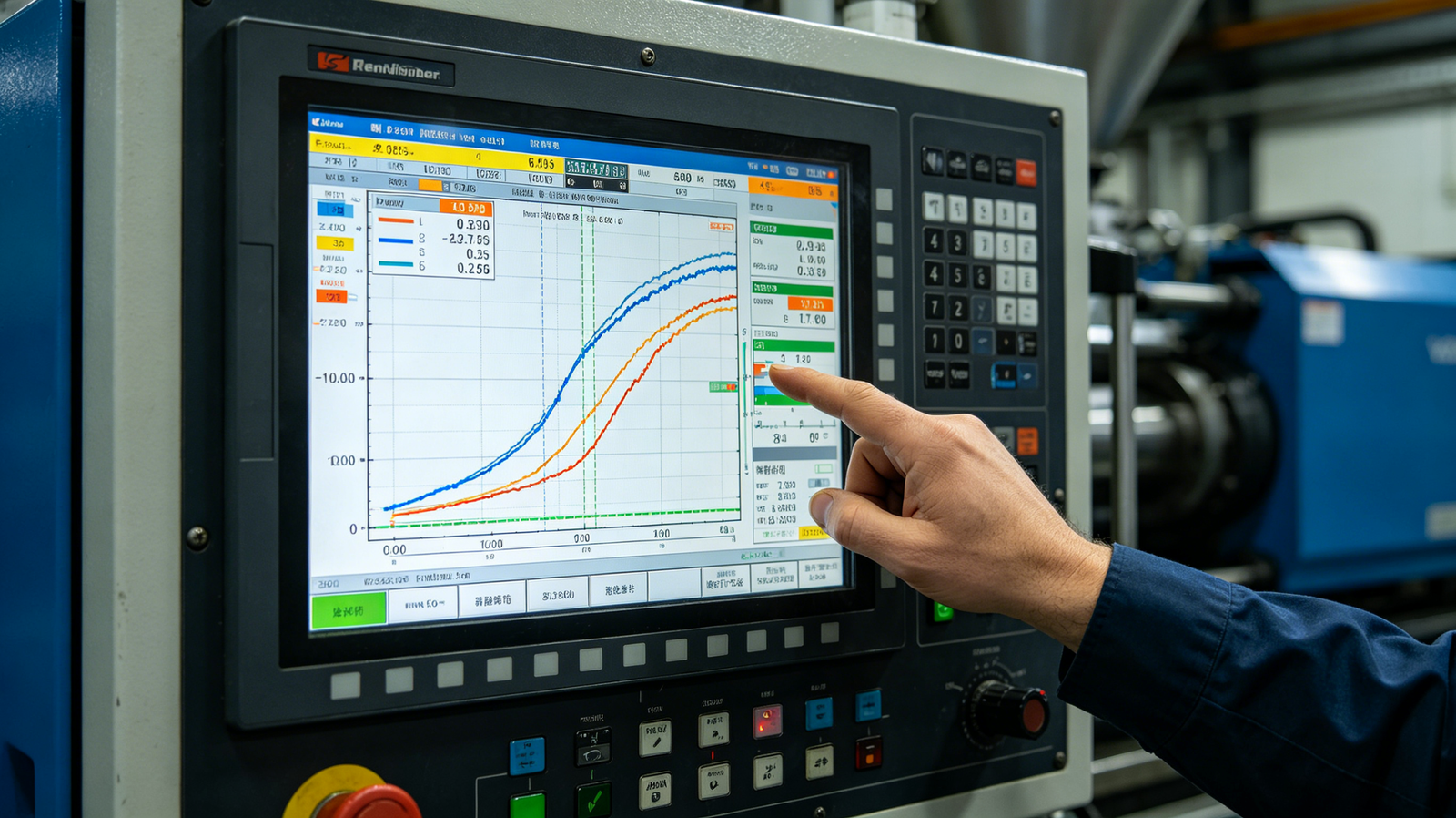
4.Processing‑parameter tuning: Appropriately reduce injection speed and control melt shear so as to lower glass‑fiber impact energy on mold surfaces.
FAQ
Q: What are the core advantages and key quality indicators of your mold‑tooling solution for glass‑filled plastic injection molding?
A: Our tooling solution focuses on anti‑abrasion performance, typical mold cavity hardness reaches 48‑52 HRC for H13 hardened steel, adopting nitriding‑plus‑PVD composite surface treatment, verified by practical mass‑production cases. The technical configuration targets stable dimensional repeatability and longer tool‑service cycles for customers’ glass‑filled component manufacturing demands.
Q: We plan to launch glass‑filled plastic injection molding projects, what documents and information should we provide for fast quotation and technical review?
A: Please submit 2D / 3D part drawings, material datasheet including glass‑fiber weight percentage, expected annual output volume and critical dimensional tolerance requirements. Send all materials via our official contact channel, we deliver initial technical feedback within 4 working hours and complete detailed quotation with tool‑steel recommendation within 12 working hours, and free manufacturability evaluation is available for qualified projects.
Q: Regarding glass‑filled‑plastic injection mold tooling, what are the rules for minimum order, delivery cycle and payment under different production‑volume targets?
A: For prototype‑level small‑batch tooling, minimum order applies; formal mass‑production mold delivery cycle ranges from 18‑28 working days subject to cavity quantity and surface‑treatment complexity. We own complete mold‑making workshop to support urgent‑order compression upon negotiation, and payment terms can be adjusted according to project scale after business communication.
Q: After we purchase anti‑abrasion molds for glass‑filled‑plastic molding, how will you handle issues including dimension deviation, abnormal surface wear or delivery delay?
A: We implement mold acceptance check before shipment. After customer receives tooling, quality complaints can be submitted within 7 working‑days upon discovery of non‑conformity. After confirmation of tool‑side defects, we provide repairing or modification solution within 48 working hours. Core mold components enjoy defined warranty period, and project contract clarifies corresponding liability clauses for delivery delay risks.
Q: Can you provide customized mold‑design and surface‑treatment adjustment according to our special working‑condition requirements for glass‑filled‑plastic parts?
A: Customized service is supported. Please offer detailed information such as exact glass‑fiber ratio, actual injection‑process parameters, target production cycles and special surface‑appearance requirements. We output customized mold‑material and surface‑treatment proposal within 3 working‑days, and extra cost will be calculated according to customized modification scope.
Conclusion
Glass‑filled plastic brings obvious abrasive threats to injection molds mainly from mechanical scraping of hard glass‑fiber particles during melt flow. The actual mold‑life loss is comprehensively affected by glass‑fiber percentage, mold‑steel grade, surface‑coating scheme, mold structural design and injection‑processing settings. It is economically efficient to arrange anti‑abrasion configuration at mold‑development stage rather than passively repairing worn molds after mass‑production starts. Project engineers need to balance component mechanical‑property requirements and long‑term tool‑investment cost to realize stable and cost‑effective serial‑manufacturing.
For expert assistance in implementing for your production needs, visit our resource center or contact us. Let’s help you scale up your manufacturing with precision and efficiency!