Injection molding defects are the most common reason molded parts are rejected, and every manufacturer faces them: sink marks, weld lines, warpage, flash, short shots, burn marks, and flow lines. Understanding what causes each defect and how to fix it is essential for producing quality parts consistently. This guide explains the 7 most common injection molding defects, their root causes, and practical solutions.
1. Sink Marks
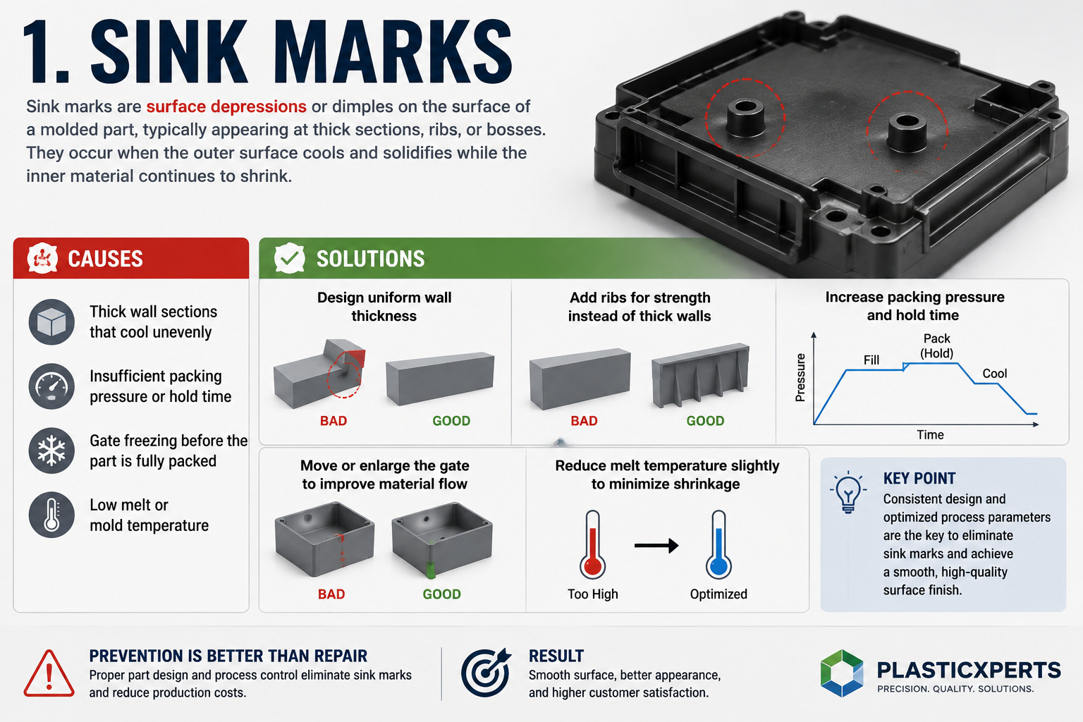
Sink marks are surface depressions or dimples on the surface of a molded part, typically appearing at thick sections, ribs, or bosses. They occur when the outer surface cools and solidifies while the inner material continues to shrink.
Causes:
- Thick wall sections that cool unevenly
- Insufficient packing pressure or hold time
- Gate freezing before the part is fully packed
- Low melt or mold temperature
Solutions:
- Design uniform wall thickness (avoid thick sections)
- Add ribs for strength instead of thick walls
- Increase packing pressure and hold time
- Move or enlarge the gate to improve material flow
- Reduce melt temperature slightly to minimize shrinkage
2. Weld Lines
Weld lines (also called knit lines) are visible lines where two flow fronts meet inside the mold. They are weak points because the material does not fully fuse at the meeting point, reducing mechanical strength.
Causes:
- Obstacles (holes, inserts, cores) splitting the melt flow
- Low melt temperature causing poor fusion
- Mold temperature too low
- Insufficient injection speed
Solutions:
- Reposition the gate to avoid splitting the flow
- Increase melt and mold temperature
- Increase injection speed so flow fronts meet while hot
- Add venting at the weld line location
- Consider overflow wells to push weak points out of the part
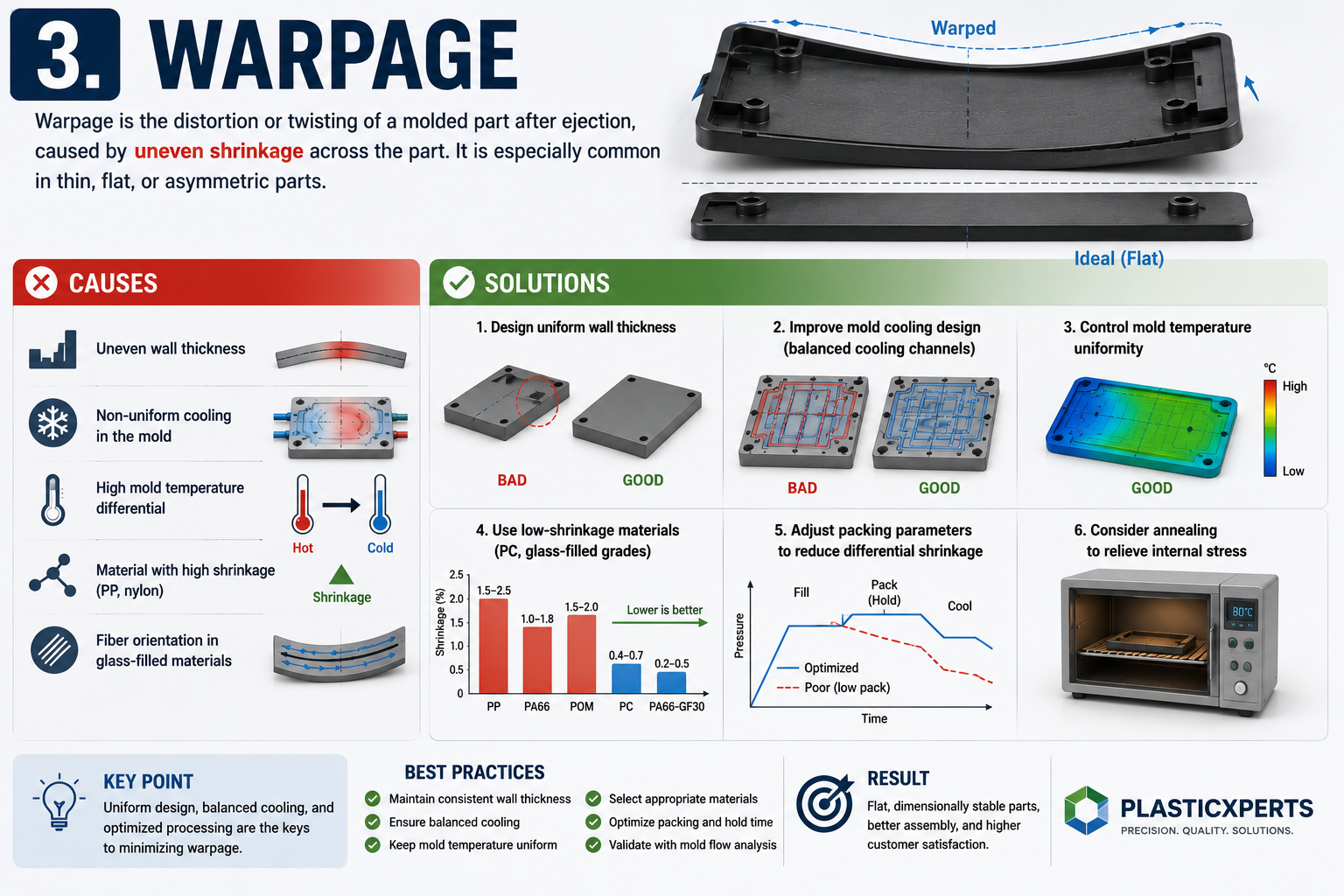
3. Warpage
Warpage is the distortion or twisting of a molded part after ejection, caused by uneven shrinkage across the part. It is especially common in thin, flat, or asymmetric parts.
Causes:
- Uneven wall thickness
- Non-uniform cooling in the mold
- High mold temperature differential
- Material with high shrinkage (PP, nylon)
- Fiber orientation in glass-filled materials
Solutions:
- Design uniform wall thickness
- Improve mold cooling design (balanced cooling channels)
- Control mold temperature uniformity
- Use low-shrinkage materials (PC, glass-filled grades)
- Adjust packing parameters to reduce differential shrinkage
- Consider annealing to relieve internal stress
4. Flash
Flash is excess thin material that escapes at the mold parting line or around ejector pins. It appears as a thin fin or burr on the part edge.
Causes:
- Clamping force too low for the injection pressure
- Mold parting line worn or damaged
- Vents too deep or dirty
- Melt temperature too high (reduced viscosity)
- Injection pressure too high
Solutions:
- Increase clamping force
- Repair or polish the mold parting line
- Clean and resize vents
- Reduce melt temperature and injection pressure
- Use a stiffer material grade if the flow is too thin
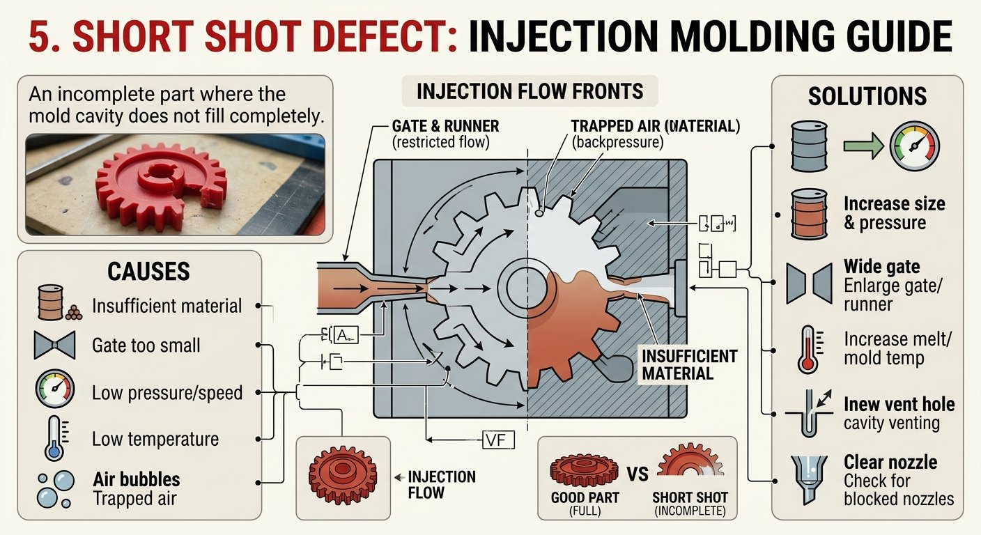
5. Short Shot
A short shot is an incomplete part where the mold cavity does not fill completely (see material flow behavior), leaving missing sections. It is one of the easiest defects to identify.
Causes:
- Insufficient material in the barrel
- Gate or runner too small, restricting flow
- Injection pressure or speed too low
- Melt temperature too low (high viscosity)
- Trapped air in the cavity
Solutions:
- Increase shot size and injection pressure
- Enlarge gate and runner dimensions
- Increase melt and mold temperature
- Add or improve cavity venting
- Check for blocked nozzles or gates
6. Burn Marks
Burn marks appear as black or brown discolored spots on the part, caused by overheating or trapped air igniting the material.
Causes:
- Trapped air compressed and overheated (dieseling)
- Melt temperature too high
- Excessive injection speed
- Poor venting
Solutions:
- Improve cavity venting to let trapped air escape
- Reduce melt temperature
- Reduce injection speed
- Add vent slots at the last fill points
7. Flow Lines
Flow lines are visible streaks or wave patterns on the part surface, occurring when the melt flows at different speeds or temperatures.
Causes:
- Melt temperature too low
- Injection speed too slow
- Mold temperature too low
- Small gate restricting smooth flow
Solutions:
- Increase melt and mold temperature
- Increase injection speed for smoother flow
- Enlarge the gate
- Use a more fluid material grade
Defect Prevention Summary
| Defect | Primary Cause | Key Solution |
|---|---|---|
| Sink marks | Thick sections, low packing | Uniform walls, more packing |
| Weld lines | Split flow, low temp | Reposition gate, higher temp |
| Warpage | Uneven shrinkage | Balanced cooling, uniform walls |
| Flash | Low clamp, worn mold | More clamp force, repair mold |
| Short shot | Low pressure, small gate | More pressure, enlarge gate |
| Burn marks | Trapped air, high temp | Better venting, lower temp |
| Flow lines | Low temp, slow speed | Higher temp, faster injection |
Conclusion
Most injection molding defects share common root causes: uneven wall thickness, improper temperature control, insufficient pressure, and poor venting. The key to defect-free molding is a combination of good part design (uniform walls, proper gate placement), well-designed molds (balanced cooling, adequate venting), and controlled process parameters. Working with a molding partner that understands these fundamentals prevents defects before they occur.
With experience in mold design, process optimization, and defect prevention, PlasticXperts helps customers produce high-quality injection molded parts. Contact our engineering team to discuss your project and receive a professional recommendation.
FAQ
What is the most common injection molding defect?
Sink marks and warpage are the most common injection molding defects, both caused by uneven shrinkage. Flash and short shots are also frequent. Most defects trace back to part design, mold design, or process parameters.
How do you fix sink marks in injection molding?
Fix sink marks by designing uniform wall thickness, increasing packing pressure and hold time, enlarging or relocating the gate, and reducing melt temperature. Adding ribs instead of thick walls also prevents sink marks.
What causes weld lines in injection molding?
Weld lines form where two melt flow fronts meet after being split by holes, inserts, or cores. They are weak points. Fix by repositioning the gate, raising melt and mold temperature, increasing injection speed, and improving venting.
Why do injection molded parts warp?
Warpage is caused by uneven shrinkage across the part, often from non-uniform wall thickness, unbalanced cooling, or high-shrinkage materials. Solutions include uniform wall design, balanced cooling channels, and low-shrinkage materials.
What causes flash in injection molding?
Flash is caused by insufficient clamping force, worn parting lines, excessive injection pressure, or low melt viscosity. Fix by increasing clamp force, repairing the mold, and adjusting pressure and temperature.
Can injection molding defects be completely eliminated?
Yes, with proper part design, well-designed molds, and controlled process parameters, defects can be minimized to near zero. A good DFM (design for manufacturability) review before tooling is the most effective way to prevent defects.