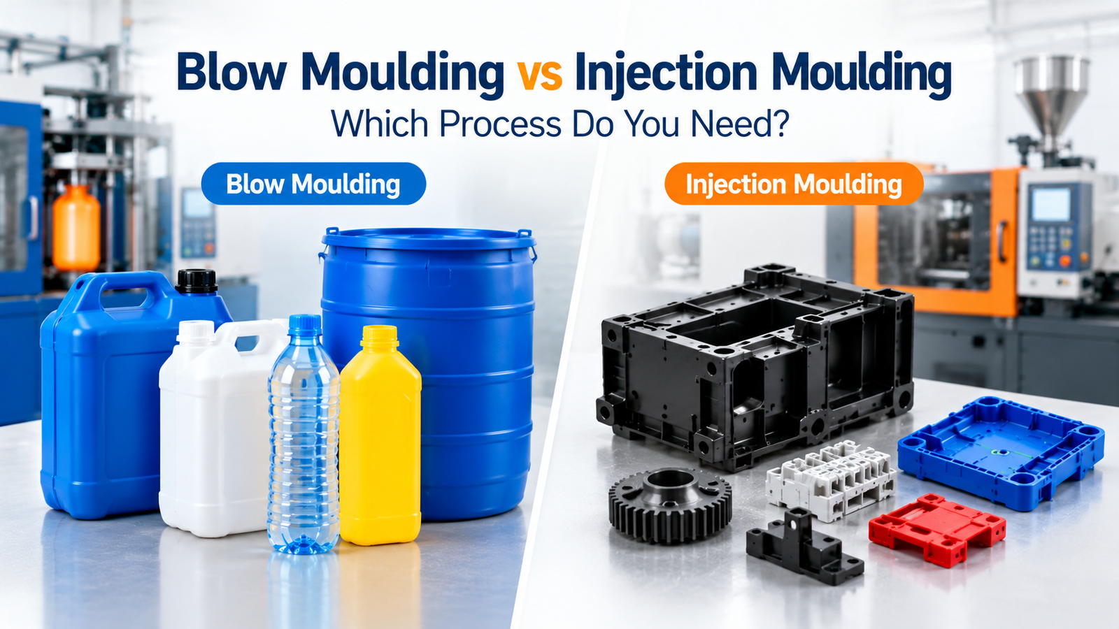
Blow moulding looks simple: heat the plastic, inflate it inside a mould, cool it, eject the part. In production it is anything but simple. Wall thickness varies with every change in parison temperature, blow pressure, and mould cooling, and a defect that appears on one side of a bottle may not appear on the other. Understanding what causes each defect is what separates a stable process from one that runs scrap.
This guide covers the most common blow moulding defects, their causes, and the process or tooling changes that fix them.
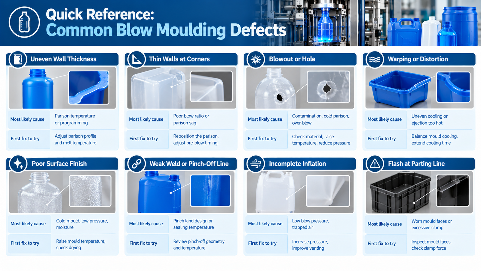
Quick Reference: Common Blow Moulding Defects
| Defect | Most likely cause | First fix to try |
|---|---|---|
| Uneven wall thickness | Parison temperature or programming | Adjust parison profile and melt temperature |
| Thin walls at corners | Poor blow ratio or parison sag | Reposition the parison, adjust pre-blow timing |
| Blowout or hole | Contamination, cold parison, over-blow | Check material, raise temperature, reduce pressure |
| Warping or distortion | Uneven cooling or ejection too hot | Balance mould cooling, extend cooling time |
| Poor surface finish | Cold mould, low pressure, moisture | Raise mould temperature, check drying |
| Weak weld or pinch-off line | Pinch land design or sealing temperature | Review pinch-off geometry and temperature |
| Incomplete inflation | Low blow pressure, trapped air | Increase pressure, improve venting |
| Flash at parting line | Worn mould faces or excessive clamp | Inspect mould faces, check clamp force |
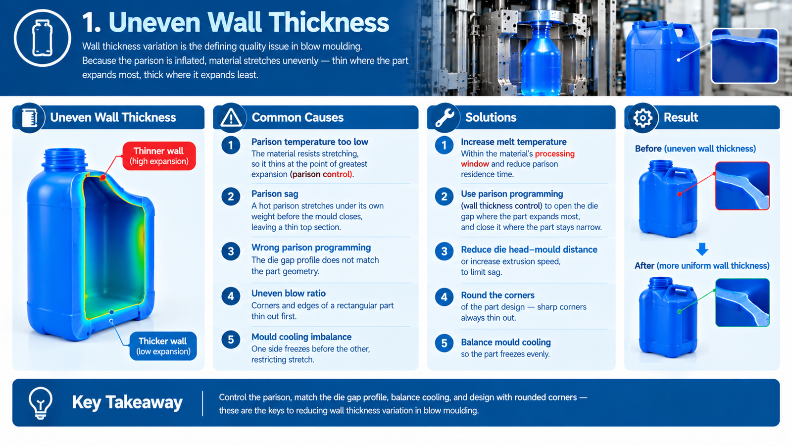
1. Uneven Wall Thickness
Wall thickness variation is the defining quality issue in blow moulding. Because the parison is inflated, material stretches unevenly — thin where the part expands most, thick where it expands least.
Causes
- Parison temperature too low: the material resists stretching, so it thins at the point of greatest expansion (parison control)
- Parison sag: a hot parison stretches under its own weight before the mould closes, leaving a thin top section
- Wrong parison programming: the die gap profile does not match the part geometry
- Uneven blow ratio: corners and edges of a rectangular part thin out first
- Mould cooling imbalance: one side freezes before the other, restricting stretch
Fixes
- Increase melt temperature within the material's processing window and reduce parison residence time
- Use parison programming (wall thickness control) to open the die gap where the part expands most, and close it where the part stays narrow
- Reduce the distance between the die head and the mould, or increase extrusion speed, to limit sag
- Round the corners of the part design — sharp corners always thin out
- Balance mould cooling so the part freezes evenly
2. Blowouts and Holes
A blowout is a local rupture where the parison tears during inflation. It usually appears at the point of maximum stretch or where contamination weakens the wall.
Causes
- Contamination in the material — regrind with foreign particles, dust, or degraded material
- Cold parison: insufficient melt temperature reduces stretchability
- Excessive blow pressure or too-fast inflation
- Sharp mould features that puncture the parison
- Weak pinch-off or a trapped air pocket that bursts
Fixes
- Control regrind quality; screen and dry material, and limit regrind percentage
- Raise melt temperature and verify it with a pyrometer rather than relying on the controller set point
- Reduce blow pressure and slow the initial inflation stage
- Radius sharp mould edges and check for damaged or burred surfaces
- Inspect the pinch-off area for correct land width and depth
3. Warping and Distortion
Blow moulded parts warp when they cool unevenly or are ejected while still soft. Thin walls make this worse, because the part has less stiffness to resist distortion while setting.
Causes
- Uneven mould cooling between the two mould halves or across the circumference
- Insufficient cooling time before ejection
- Part removed while core temperature is still high
- Uneven wall thickness causing differential shrinkage
- Post-mould handling while the part is hot
Fixes
- Balance cooling channels in both mould halves; verify actual mould surface temperature across the cavity (heat transfer fundamentals apply)
- Extend cooling time, or reduce cycle time only after confirming stable dimensions
- Use a take-out fixture or cooling jig that supports the part after ejection
- Fix wall thickness variation first — warpage and thickness variation are usually the same problem
- Avoid stacking hot parts on top of each other
4. Poor Surface Finish
Surface defects range from a rough orange-peel texture to streaks, dull patches, and visible flow marks.
Causes
- Mould surface temperature too low, causing premature freezing against the cavity wall
- Wet material: moisture produces streaks and silver marks
- Low blow pressure, so the parison does not fully contact the mould surface
- Contaminated mould surface from release agents or degraded material
- Cold parison with insufficient flow
Fixes
- Raise mould temperature and increase cooling channel flow rather than lowering it where hot spots exist
- Verify drying is correct for the material and check the dryer dew point
- Increase blow pressure so the parison replicates the mould texture
- Clean the mould and stop using release agents where possible
- Check for degraded material in the die head and purge thoroughly
5. Weak Weld or Pinch-Off Lines
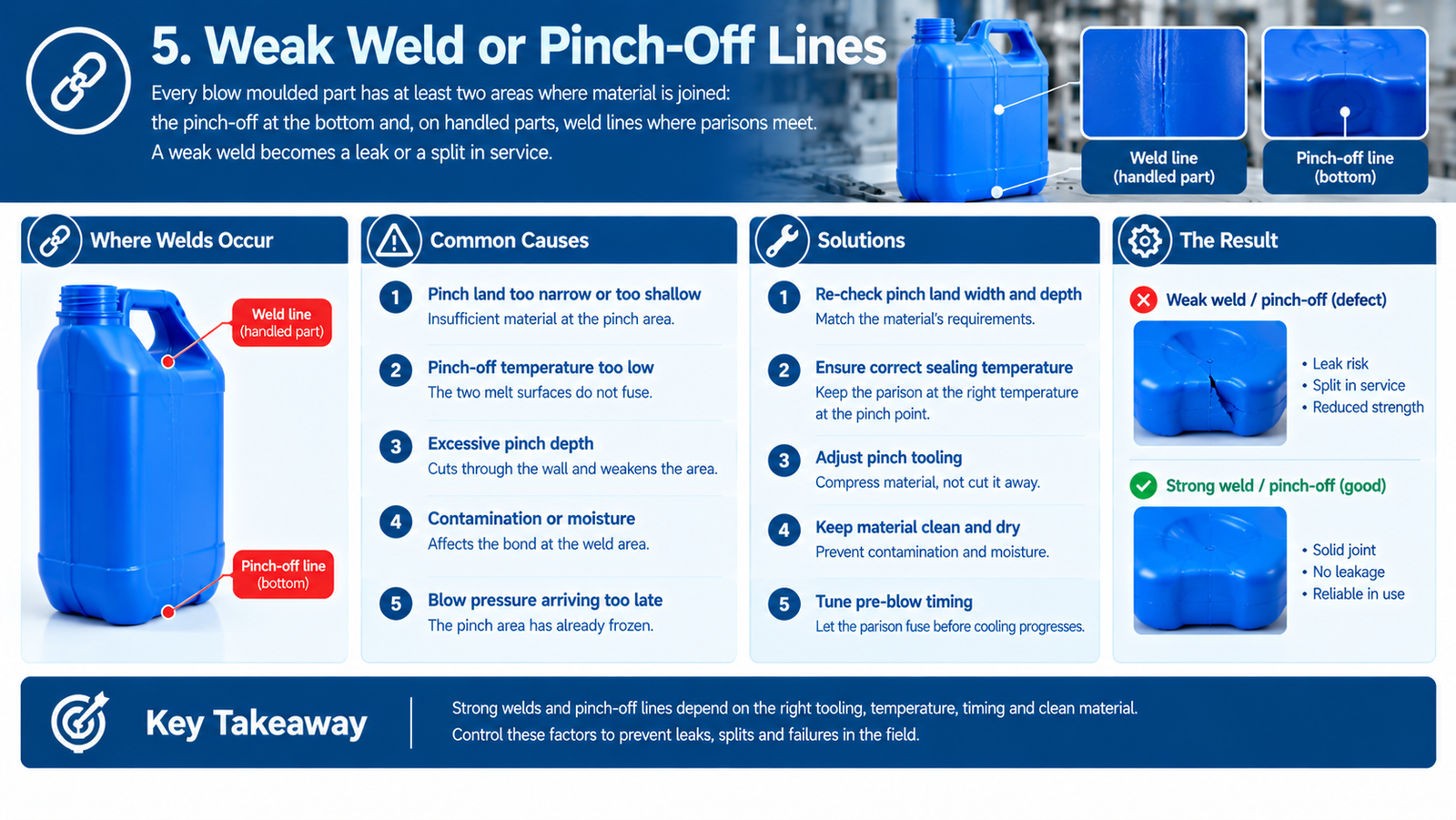
Every blow moulded part has at least two areas where material is joined: the pinch-off at the bottom and, on handled parts, weld lines where parisons meet. A weak weld becomes a leak or a split in service.
Causes
- Pinch land too narrow or too shallow
- Pinch-off temperature too low, so the two melt surfaces do not fuse
- Excessive pinch depth cutting through the wall
- Contamination or moisture at the weld area
- Blow pressure arriving too late, while the pinch area has already frozen
Fixes
- Re-check pinch land width and depth against the material's requirements
- Ensure the parison is at the correct sealing temperature at the pinch point
- Adjust pinch tooling so material is compressed, not cut away
- Keep material clean and dry
- Tune pre-blow timing so the parison fuses before cooling progresses
6. Incomplete Inflation and Short Blow
The parison does not fully expand, leaving flat areas, soft corners, or features that never form.
Causes
- Blow pressure too low for the part size and material
- Air trapped between the parison and mould wall, blocking expansion
- Parison too cold, so it will not stretch into corners
- Blow pin blocked, leaking, or misaligned
- Insufficient pre-blow, or pre-blow pressure not matched to the parison
Fixes
- Increase blow pressure and verify it at the mould, not only at the regulator
- Add or clear mould venting so trapped air escapes
- Raise melt temperature and review parison profile
- Inspect the blow pin for blockage, wear, and alignment
- Tune pre-blow separately from final blow
7. Flash, Parting Line and Neck Defects
Flash, mismatched parting lines, and out-of-tolerance necks are tooling and clamp related rather than melt related.
Causes
- Worn or damaged parting line faces
- Clamp force too low for the blow pressure used
- Mould alignment pin wear causing mismatch between halves
- Neck and thread inserts worn, or calcified from cooling water
- Excessive blow pressure forcing material into gaps
Fixes
- Inspect and rework parting line faces; replace damaged inserts
- Verify clamp force and check for mould deflection under pressure
- Replace alignment pins and bushings, and verify mould closing before production
- Service neck and thread tooling; check the thread dimensions with go and no-go gauges
- Reduce blow pressure where the tooling cannot hold it
8. Contamination, Black Specks and Streaks
Black specks and streaks are a material and machine cleanliness problem, and they rarely resolve without intervention.
Causes
- Degraded material in the extruder, die head, or flow channels
- Contaminated regrind or mixed-material recycling
- Carbon build-up from overheating or long residence time
- Dust or dirt on pellets
- Worn screw and barrel producing degraded melt
Fixes
- Purge the machine; if specks persist, strip and clean the die head
- Control regrind: keep material types separate, limit regrind ratio, keep it clean and dry
- Reduce melt temperature and residence time
- Cover material handling systems and check for dust ingress
- Inspect screw and barrel wear during scheduled maintenance
Prevention: The Variables That Actually Control Quality
Most blow moulding defects trace back to five process variables. Controlling these is more effective than chasing defects individually.
| Variable | What it controls | How to verify |
|---|---|---|
| Melt temperature | Stretchability, surface finish, weld strength | Pyrometer at the die, not just the controller |
| Parison profile | Wall thickness distribution | Programmed profile reviewed against sectioned parts |
| Blow pressure and timing | Inflation, detail replication | Pressure gauge at the mould, pre-blow tuned separately |
| Mould temperature | Cooling rate, surface finish, warpage | Surface contact probes across the cavity |
| Cooling time | Dimensional stability, warpage | Measured part dimensions, not visual judgement |
Verifying the Finished Part
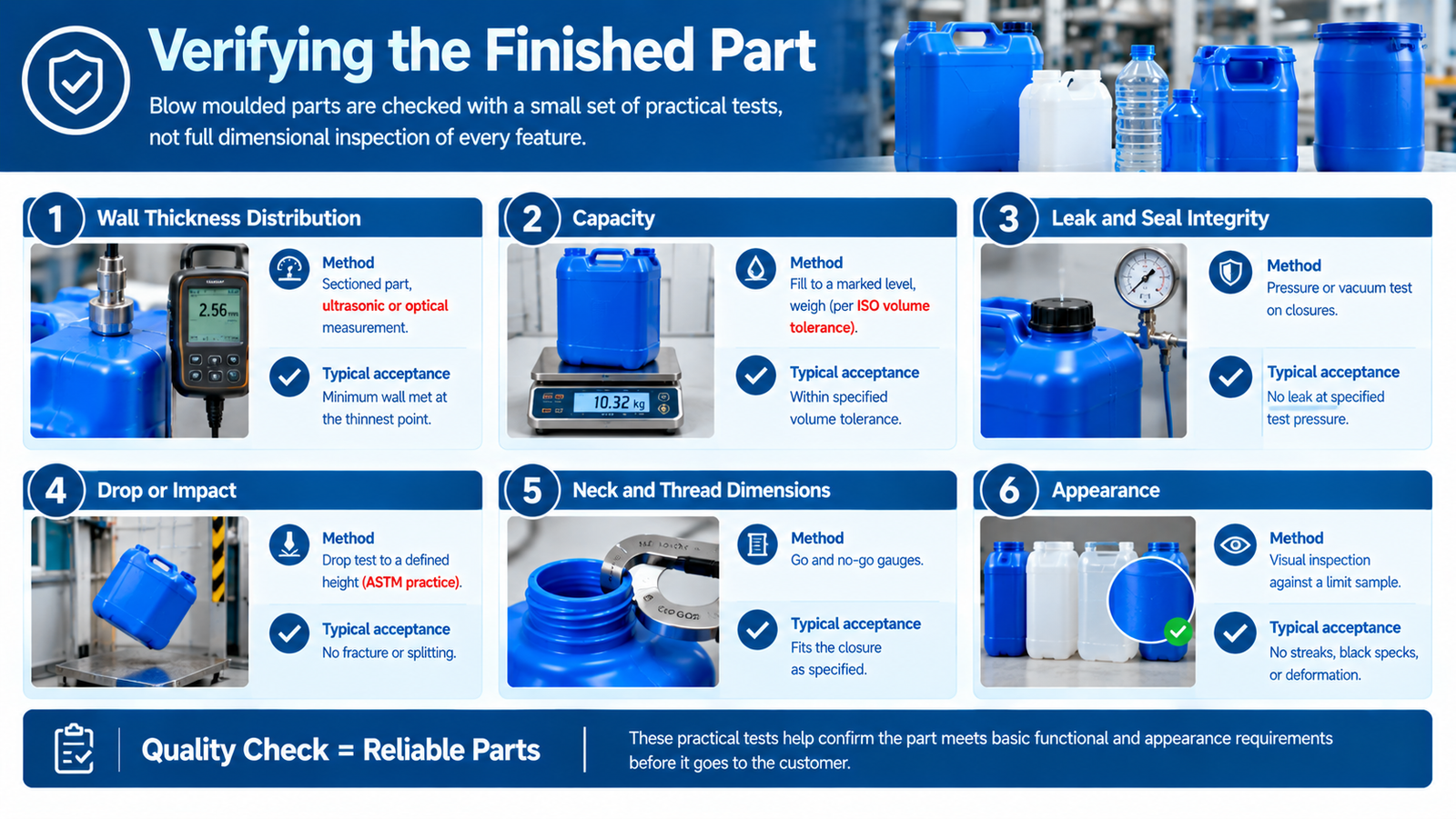
Blow moulded parts are checked with a small set of practical tests, not full dimensional inspection of every feature.
| Check | Method | Typical acceptance |
|---|---|---|
| Wall thickness distribution | Sectioned part, ultrasonic or optical measurement | Minimum wall met at the thinnest point |
| Capacity | Fill to a marked level, weigh (per ISO volume tolerance) | Within specified volume tolerance |
| Leak and seal integrity | Pressure or vacuum test on closures | No leak at specified test pressure |
| Drop or impact | Drop test to a defined height (ASTM practice) | No fracture or splitting |
| Neck and thread dimensions | Go and no-go gauges | Fits the closure as specified |
| Appearance | Visual inspection against a limit sample | No streaks, black specks, or deformation |
Conclusion
Blow moulding defects almost always come back to three things: parison temperature and profile, mould cooling, and mould tooling condition. Wall thickness variation is the source defect — fix it and most other problems disappear with it. Sectioning a part and measuring the actual wall distribution is the single most useful diagnostic step in blow moulding (standard plastics engineering practice), and it costs one part.
With experience in both blow moulding and injection moulding, plus in-house tooling and dimensional inspection, we support projects from part design and tooling through stable volume production. Send us your drawing and container specification to discuss the process, tooling, and quality plan.
FAQ
What causes thin walls in blow moulding?
Thin walls come from the parison stretching more than intended — from low melt temperature, parison sag, an unmatched parison profile, or sharp corners that expand furthest. Adjusting the parison profile, raising melt temperature, and rounding part corners are the standard fixes.
How do I fix blowouts in blow moulding?
Blowouts usually come from contamination, a cold parison, or excessive blow pressure. Check regrind quality, raise melt temperature and verify it with a pyrometer, reduce inflation pressure, and radius any sharp mould features that could puncture the parison.
Why do blow moulded parts warp?
Warping is caused by uneven cooling or ejecting the part while it is still hot, and it is made worse by uneven wall thickness. Balance the mould cooling, extend cooling time, support the part after ejection, and correct wall thickness variation.
What causes weak weld or pinch-off lines?
Weak welds result from pinch land geometry that is too narrow or shallow, pinch temperature too low for proper fusion, excessive pinch depth that cuts the wall, or blow pressure arriving after the pinch area has frozen. Review the pinch tooling and sealing temperature.
What is the most important process variable in blow moulding?
Melt temperature and parison temperature control are the most influential variables, because they govern stretchability, surface finish, and weld strength. Verify temperature with a pyrometer at the die rather than trusting the controller set point alone.
How do you check wall thickness on a blow moulded part?
The most reliable method is to section a finished part and measure the wall at several points with a micrometer or optical gauge. Ultrasonic thickness gauges allow non-destructive checks on production parts. Minimum wall thickness at the thinnest point is the specification that matters.