Shrinkage is the reason a mould is never cut to the exact size of the finished part. Every plastic shrinks as it cools from melt to solid, and the mould cavity must be made larger to compensate. Get the shrinkage value wrong by even a fraction of a percent and a dimensionally critical part will not fit — and correcting it means cutting steel.
This guide explains what mould shrinkage is, gives typical shrinkage rates by material, shows how to calculate cavity dimensions, and covers the factors that make real shrinkage differ from the data sheet value.
What Mould Shrinkage Is
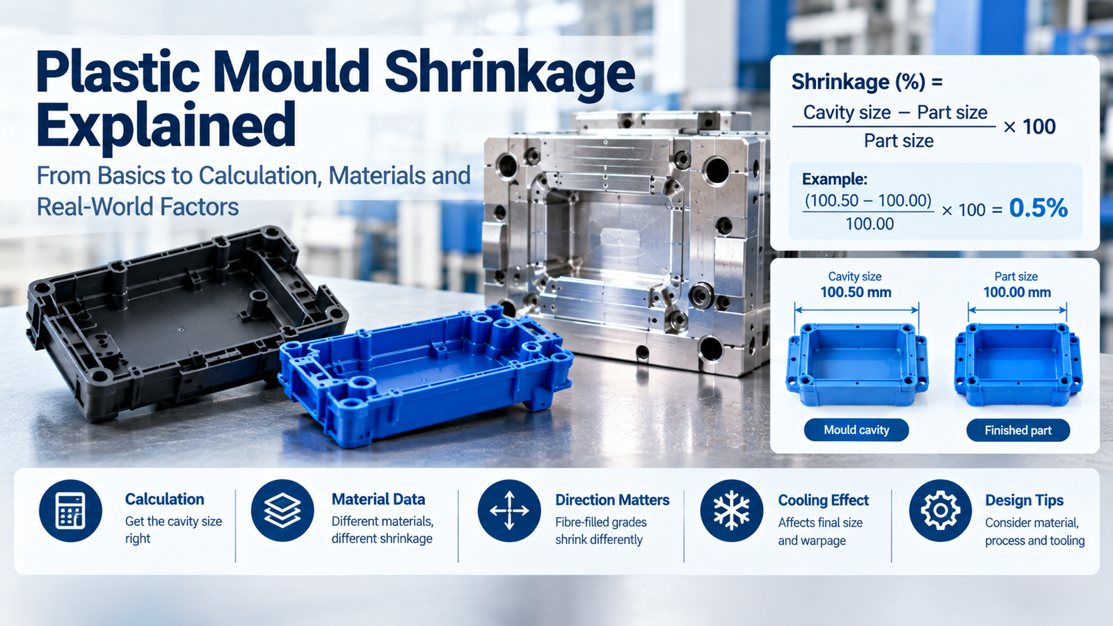
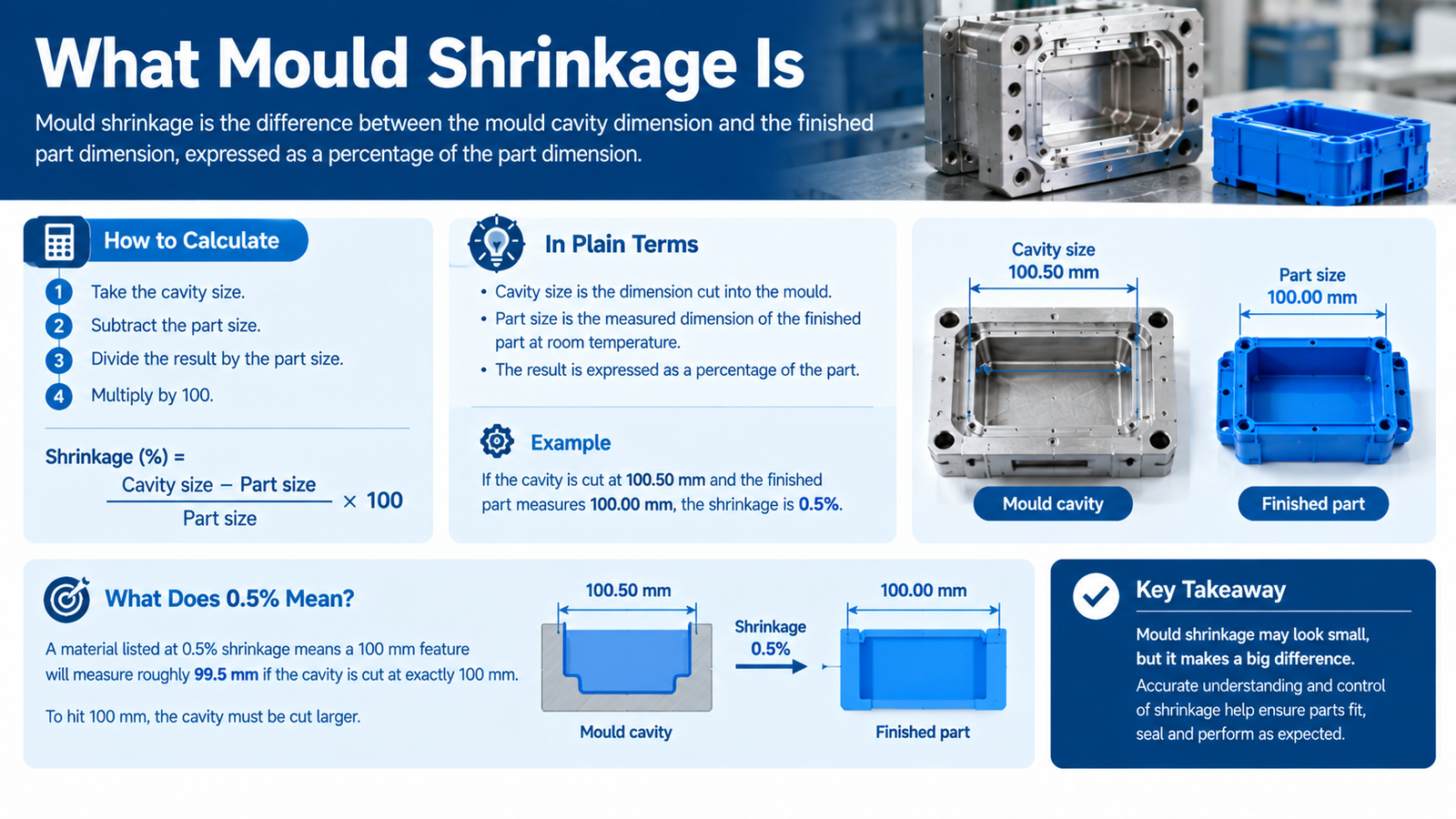
Mould shrinkage is the difference between the mould cavity dimension and the finished part dimension, expressed as a percentage of the part dimension.
To work it out, take the cavity size, subtract the part size, divide the result by the part size, and multiply by 100.
In plain terms: cavity size is the dimension cut into the mould, part size is the measured dimension of the finished part at room temperature, and the result is expressed as a percentage of the part.
For example, if the cavity is cut at 100.50 mm and the finished part measures 100.00 mm, the shrinkage is 0.5 percent.
A material listed at 0.5 percent shrinkage means a 100 mm feature will measure roughly 99.5 mm if the cavity is cut at exactly 100 mm. To hit 100 mm, the cavity must be cut larger.
Calculating Cavity Dimensions From Shrinkage
The simple approximation used on the shop floor is to multiply the part size by one plus the shrinkage rate. For a 100 mm part in a material with 1.2 percent shrinkage, that is 100 multiplied by 1.012, giving a cavity size of 101.20 mm.
The more accurate form divides the part size by one minus the shrinkage rate, because shrinkage is defined against the part and not the mould. The same 100 mm part gives 100 divided by 0.988, or 101.21 mm.
Worked example for PA66 at 1.2 percent shrinkage, target dimension 100.00 mm:
| Method | Calculation | Cavity size | Resulting part |
|---|---|---|---|
| Approximation | 100 × 1.012 | 101.20 mm | about 99.98 mm |
| Accurate | 100 ÷ 0.988 | 101.21 mm | 100.00 mm |
For small dimensions the difference is negligible. For large parts — a 600 mm automotive trim panel at 1.2 percent shrinkage, for example — the two methods diverge by several hundredths of a millimetre, which is enough to matter on a controlled dimension.
Typical Shrinkage Rates by Material
The table below lists common mould shrinkage values for unfilled grades, cross-checked against published resin data. Always confirm against the specific resin grade data sheet supplied by the manufacturer, because additives and grades shift these numbers.
| Material | Type | Shrinkage range (%) | Typical design value (%) |
|---|---|---|---|
| ABS | Amorphous | 0.4 – 0.7 | 0.5 |
| Polystyrene (PS) | Amorphous | 0.4 – 0.7 | 0.5 |
| PMMA (acrylic) | Amorphous | 0.2 – 0.8 | 0.4 |
| Polycarbonate (PC) | Amorphous | 0.5 – 0.8 | 0.6 |
| PC/ABS blend | Amorphous | 0.5 – 0.7 | 0.6 |
| Rigid PVC | Amorphous | 0.2 – 0.5 | 0.4 |
| PPO / PPE | Amorphous | 0.5 – 0.7 | 0.6 |
| PA6 (nylon 6) | Semi-crystalline | 0.8 – 1.5 | 1.2 |
| PA66 | Semi-crystalline | 0.8 – 1.5 | 1.2 |
| POM (acetal) | Semi-crystalline | 1.8 – 2.5 | 2.0 |
| PBT | Semi-crystalline | 1.3 – 2.2 | 1.7 |
| PP (homopolymer) | Semi-crystalline | 1.0 – 2.5 | 1.6 |
| HDPE | Semi-crystalline | 1.5 – 3.5 | 2.5 |
| LDPE | Semi-crystalline | 1.5 – 3.5 | 2.5 |
| PET (semi-crystalline) | Semi-crystalline | 1.2 – 2.0 | 1.5 |
| PPS | Semi-crystalline | 0.6 – 1.4 | 1.0 |
| PEEK | Semi-crystalline | 1.1 – 1.5 | 1.3 |
| TPU | Semi-crystalline | 0.5 – 1.5 | 1.0 |
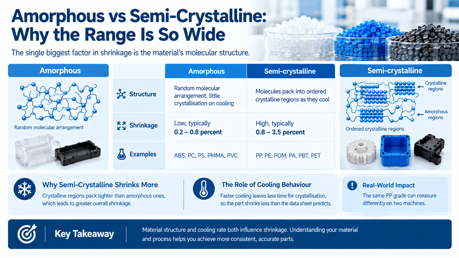
Amorphous vs Semi-Crystalline: Why the Range Is So Wide
The single biggest factor in shrinkage is the material's molecular structure.
| Structure | Behaviour | Shrinkage | Examples |
|---|---|---|---|
| Amorphous | Random molecular arrangement, little crystallisation on cooling | Low, typically 0.2 – 0.8 percent | ABS, PC, PS, PMMA, PVC |
| Semi-crystalline | Molecules pack into ordered crystalline regions as they cool | High, typically 0.8 – 3.5 percent | PP, PE, POM, PA, PBT, PET |
Semi-crystalline plastics shrink more because the crystalline regions pack tighter than the amorphous ones, an effect driven by cooling behaviour. This also makes them more sensitive to cooling rate: faster cooling leaves less time for crystallisation, so the part shrinks less than the data sheet predicts. That is why the same PP grade can measure differently on two machines running different cooling.
Fibre-Filled Grades: Shrinkage in Two Directions
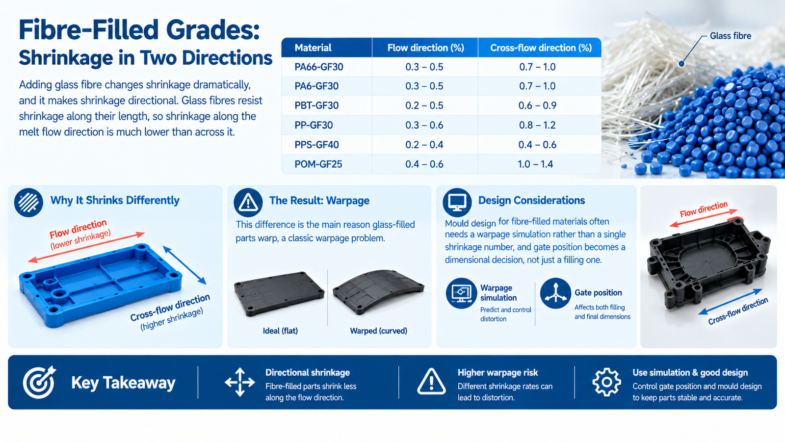
Adding glass fibre changes shrinkage dramatically, and it makes shrinkage directional. Glass fibres resist shrinkage along their length, so shrinkage along the melt flow direction is much lower than across it.
| Material | Flow direction (%) | Cross-flow direction (%) |
|---|---|---|
| PA66-GF30 | 0.3 – 0.5 | 0.7 – 1.0 |
| PA6-GF30 | 0.3 – 0.5 | 0.7 – 1.0 |
| PBT-GF30 | 0.2 – 0.5 | 0.6 – 0.9 |
| PP-GF30 | 0.3 – 0.6 | 0.8 – 1.2 |
| PPS-GF40 | 0.2 – 0.4 | 0.4 – 0.6 |
| POM-GF25 | 0.4 – 0.6 | 1.0 – 1.4 |
This difference is the main reason glass-filled parts warp, a classic warpage problem. A flat panel that shrinks 0.4 percent one way and 0.9 percent the other cannot stay flat — it curls. Mould design for fibre-filled materials often needs a warpage simulation rather than a single shrinkage number, and gate position becomes a dimensional decision, not just a filling one.
What Changes Real Shrinkage in Production
The data sheet value is only a starting point. Actual shrinkage in the mould depends on the following.
| Factor | Effect on shrinkage |
|---|---|
| Wall thickness | Thicker sections cool slower and crystallise more, so they shrink more |
| Melt temperature | Higher melt temperature generally increases shrinkage |
| Mould temperature | Hotter mould means slower cooling, more crystallisation, higher shrinkage |
| Holding pressure and time | Higher packing reduces shrinkage by forcing in more material |
| Gate size and location | Affects flow orientation, packing, and local shrinkage |
| Flow direction | Fibre and molecular orientation create directional shrinkage |
| Part geometry | Ribs, bosses, and thickness changes cause local differences |
| Post-mould environment | Parts continue to shrink slightly after ejection, and nylons swell as they absorb moisture |
The last two rows are why shrinkage is not uniform across a part — and why the practical answer is not one number but a tooling correction process.
Post-Mould Shrinkage and Moisture
Two effects continue after the part leaves the mould.
Post-mould shrinkage: parts relax and shrink slightly more over the first hours and days, especially semi-crystalline materials.
Moisture absorption: nylon absorbs moisture and swells. A PA66 part can grow measurably within days of moulding in humid air, and the change can be comparable in size to the moulding shrinkage itself. Nylon absorbs roughly 1.5 to 8.5 percent moisture by weight, with a corresponding dimensional change.
For nylon parts this matters more than the shrinkage data sheet in practice. Parts measured dry may fail to fit when conditioned to the customer's environment, so dimensional specifications for nylon should always state the conditioning state used for the measurement, following a defined conditioning standard such as ASTM conditioning practice.
How Shrinkage Is Handled in Tooling
A professional tooling process handles shrinkage in three stages.
First, design stage: cavity dimensions are scaled using the resin supplier's shrinkage data, adjusted for wall thickness, gate location, and flow orientation.
Second, simulation: for complex or fibre-filled parts, a filling and warpage simulation predicts differential shrinkage and shows where correction is needed before steel is cut.
Third, correction stage: the first article is measured and compared against the drawing. Dimensions can then be adjusted by removing steel to reduce a dimension or, in limited cases, by adding steel and re-machining.
Note the asymmetry. Cutting steel to make a dimension smaller is straightforward. Making it larger requires welding and re-machining, which is slower and riskier. This is why critical dimensions are usually cut slightly oversize and trimmed down — never the reverse.
What to Provide Your Moulder
Shrinkage is the moulder's responsibility, but the buyer controls the inputs that decide it.
| Provide | Why it matters |
|---|---|
| The exact resin grade, including supplier and grade code | Shrinkage varies between grades of the same material |
| Wall thickness at each feature | Thickness drives cooling rate and shrinkage |
| Which dimensions are critical, referenced to ISO dimensional standards | These receive simulation and tooling-correction attention |
| Flow direction requirements, if any | Determines gating and expected anisotropy |
| Conditioning state for nylon parts | Dry versus conditioned changes the measured size |
| Cosmetic and texture requirements | Texture depth affects local surface shrinkage |
Common Mistakes
| Mistake | Consequence |
|---|---|
| Using a generic shrinkage figure instead of the grade data | Dimensions off from the first shot |
| Applying one shrinkage value to a fibre-filled part | Parts warp, because flow and cross-flow differ |
| Ignoring wall thickness variation | Local shrinkage differs, causing sink marks and warp |
| Measuring nylon parts dry and calling it final | Parts move after conditioning, and assembly fails |
| Cutting cavities undersize | Correction requires welding, which is costly and slow |
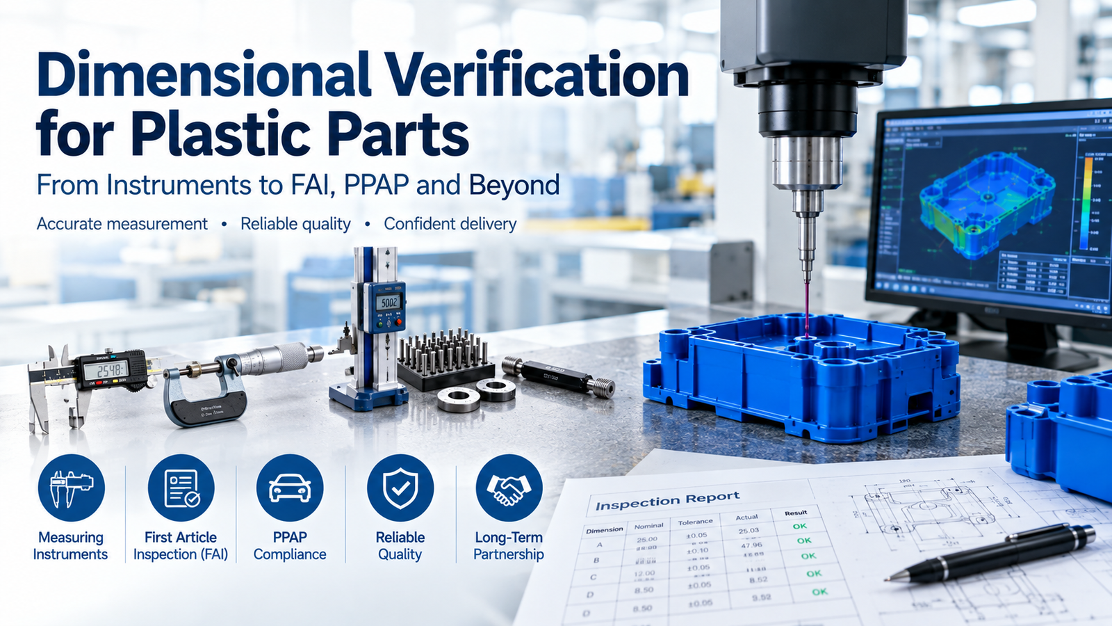
| No measurement of the first article | No basis for correction, and disputes later |
Conclusion
Shrinkage is not a single number. It is a material property modified by wall thickness, gate location, cooling, packing, and fibre orientation. The data sheet gives the starting point, and measurement plus correction gives the result — standard plastics engineering practice. Handling it properly means using the exact grade data, simulating where geometry is complex or fibre-filled, and measuring the first article before approving production.
With in-house mould design and tooling manufacture, plus filling and warpage simulation and dimensional verification of first articles, we account for shrinkage rather than discovering it. Send us your drawing and resin grade for a DFM review that includes the shrinkage strategy.
FAQ
What is a normal shrinkage rate for plastic?
It depends on the material type. Amorphous plastics such as ABS, PC, and PS shrink roughly 0.2 to 0.8 percent, while semi-crystalline plastics such as PP, PE, POM, and nylon shrink 0.8 to 3.5 percent. Always use the specific grade data sheet rather than a general figure.
How do I calculate mould dimensions from shrinkage?
Divide the target part dimension by one minus the shrinkage. For a 100 mm part in a material with 1.2 percent shrinkage: 100 divided by 0.988 equals 101.21 mm cavity size. The simple approximation of multiplying by one plus the shrinkage is close enough for small parts but drifts on large ones.
Why do glass-filled plastics shrink differently in different directions?
Glass fibres align with the melt flow and resist shrinkage along their length. Shrinkage along the flow direction can be roughly half the cross-flow value, for example 0.3 percent versus 0.8 percent in PA66-GF30. This difference is the main cause of warpage in fibre-filled parts.
Does wall thickness affect shrinkage?
Yes. Thicker sections cool more slowly, allowing more crystallisation in semi-crystalline materials and therefore more shrinkage. Uneven wall thickness also creates uneven shrinkage, which appears as warpage and sink marks.
Why do nylon parts change size after moulding?
Nylon absorbs moisture from the air and swells. PA66 can absorb several percent of its weight in water, producing a dimensional change comparable to moulding shrinkage. Dimensional specifications for nylon parts should state the conditioning state used for measurement.
Can shrinkage be corrected after the mould is made?
Partly. Dimensions can be reduced by removing steel, which is a normal correction step. Increasing a dimension requires welding and re-machining, which is slower and riskier. This is why critical dimensions are usually cut slightly oversize and trimmed to size after measuring the first article.