Non-uniform wall thickness is the most expensive design mistake in injection moulding, because it cannot be fixed in the tool and it cannot be fixed in the process. It shows up as sink marks on cosmetic surfaces, warpage that will not straighten, short shots in the thin sections, long cycles driven by the thick ones, and parts that fail in the field months after they were accepted.
This guide sets out what wall thickness variation actually does to a part, the ratios that keep a design mouldable, and the design fixes that cost nothing before the tool is cut and a fortune afterwards.
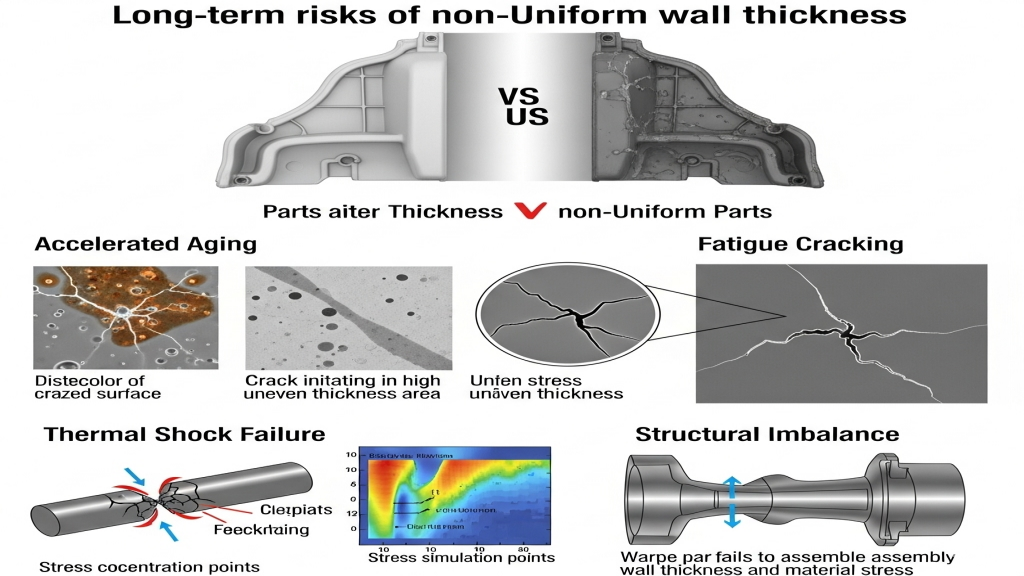
The physics in one paragraph
Molten plastic shrinks as it cools, and thick sections cool last. A thick section therefore continues to shrink while the thin section beside it is already rigid, and that mismatch has only two possible outcomes: the surface sinks, or the part bends. Everything else in this guide follows from that single mechanism.
Cooling time follows the square of wall thickness, which is why a thick section is disproportionately expensive:
| Wall thickness (mm) | Relative cooling time | Relative cycle time |
|---|---|---|
| 1.0 | 1.0 | 1.0 |
| 1.5 | 2.3 | 1.6 |
| 2.0 | 4.0 | 2.2 |
| 3.0 | 9.0 | 4.0 |
| 4.0 | 16.0 | 6.5 |
Doubling wall thickness quadruples cooling time. A part with one 4 mm section and the rest at 2 mm runs at the cycle time of the 4 mm section, not the average — which is why wall thickness variation is a cost problem before it is a quality problem.
What each defect actually comes from
| Defect | Mechanism | Where it appears |
|---|---|---|
| Sink marks | Thick section shrinks after the surface freezes | Cosmetic face over ribs, bosses, thick corners |
| Warpage | Differential shrinkage through the section | Long flat parts, parts with one thick edge |
| Short shots | Thin section freezes before it fills | Thin ribs, thin walls far from the gate |
| Voiding | Internal shrinkage pulls a vacuum | Very thick sections, heavy bosses |
| Weld line weakness | Cold melt fronts meeting | Behind cores, in thin sections |
| Dimensional drift | Uneven crystallisation and post-mould shrink | Tight-tolerance features |
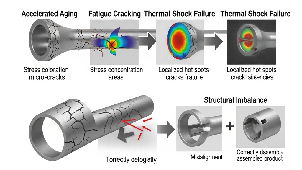
| Stress cracking | Moulded-in stress releases later | Around inserts, at sharp thickness steps |
| Long cycles | Thickest section sets the cooling time | Whole part |
The two that cost most in practice are sink marks and warpage, because both are visible to the customer and neither can be polished out.
The ratios that keep a design mouldable
| Rule | Value | Why |
|---|---|---|
| Nominal wall | 1.5 – 3.0 mm for most engineering plastics | Below 1.5 mm is hard to fill, above 3.0 mm is slow |
| Adjacent wall ratio | 1.2:1 ideal, 1.5:1 maximum | Above 1.5 the sink or warp is unavoidable |
| Maximum section | 4.0 mm for unfilled grades | Thicker risks voids and long cycles |
| Transition length | 3:1 to 4:1 (length : thickness step) | Gradual change lets melt flow without stalling |
| Rib thickness | 50 – 60% of nominal wall | Prevents sink over the rib |
| Boss wall | 60% of nominal wall | Same reason, plus ejection strength |
| Corner radius | 0.5 × wall thickness minimum | Sharp corners concentrate stress |
The 1.5:1 ratio is the number to remember. A 2 mm panel can carry a 3 mm feature; it cannot carry a 4 mm one without a visible sink on the other side.
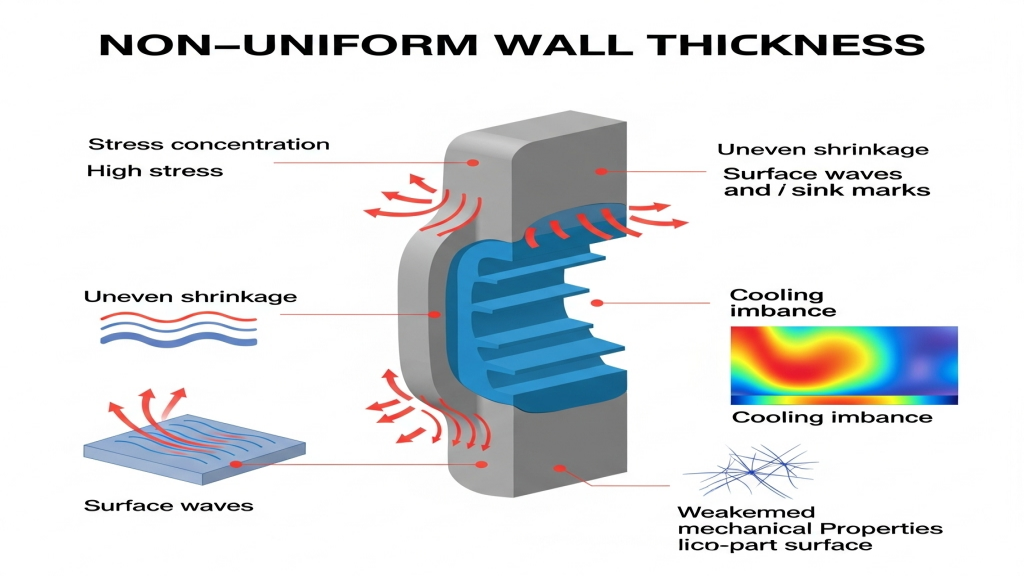
How to transition between thicknesses
A step change in wall thickness is the worst case: the melt accelerates into the thin section, the thick section packs unevenly, and the corner where they meet becomes a stress riser.
| Transition | Result | Recommendation |
|---|---|---|
| Sharp step (90°) | Sink at the step, stress concentration, flow hesitation | Avoid |
| Chamfer 45° | Better flow, still concentrates stress | Minimum acceptable |
| Taper 1:3 | Smooth fill, gradual cooling, low stress | Design target |
| Taper 1:4 or longer | Best for cosmetic parts and thick sections | Use where space allows |
| Cored-out thick section | Removes material instead of adding it | Usually the best answer |
The most useful design move is not to blend the thickness but to remove it: core out the thick section from the non-cosmetic side. A 6 mm solid boss becomes a 2 mm walled tube with a 2 mm base, and every problem in this guide disappears.
Structural features: where thickness variation hides
| Feature | Common mistake | Correct approach |
|---|---|---|
| Ribs | Rib as thick as the wall | 50 – 60% of wall, generous draft |
| Bosses | Solid boss standing on a thin panel | Cored boss, 60% wall, radiused base, gussets |
| Corners | Sharp internal corner at a thick junction | Generous radius, uniform wall through the corner |
| Inserts | Thick boss around a metal insert | Wall matched to the insert, pre-heat the insert |
| Snap fits | Thin flexing arm next to a thick body | Uniform flexing section, taper into the body |
| Threaded bosses | Thick cylinder | Cored, with metal insert for repeated assembly |
Bosses deserve special attention because they combine three risks at once: a thick section, a sharp base radius and a stress concentration. Our guide to reinforcing rib design covers the rib side in detail, and the thick-section shrinkage behaviour is treated in shrinkage in thick ABS parts.
What the process can and cannot fix
| Process lever | Can it fix wall variation? | Limit |
|---|---|---|
| Higher packing pressure | Reduces sink depth | Cannot fill a void inside a thick section |
| Longer packing time | Improves thick-section packing | Only until the gate freezes |
| Higher melt temperature | Improves flow into thin sections | Increases shrinkage and cycle time |
| Higher mould temperature | Reduces stress, improves surface | Worse sink, longer cycle |
| Slower injection | More uniform fill | Weld lines and flow marks |
| Local cooling | Balances thick and thin | Helps warp, not sink |
| Gate repositioning | Puts packing where it is needed | Limited by part geometry |
The honest summary: the process can recover 0.05 to 0.15 mm of sink and a degree or two of warp. It cannot recover a 1 mm wall step. If the design has a 2:1 wall ratio, no process setting saves it.
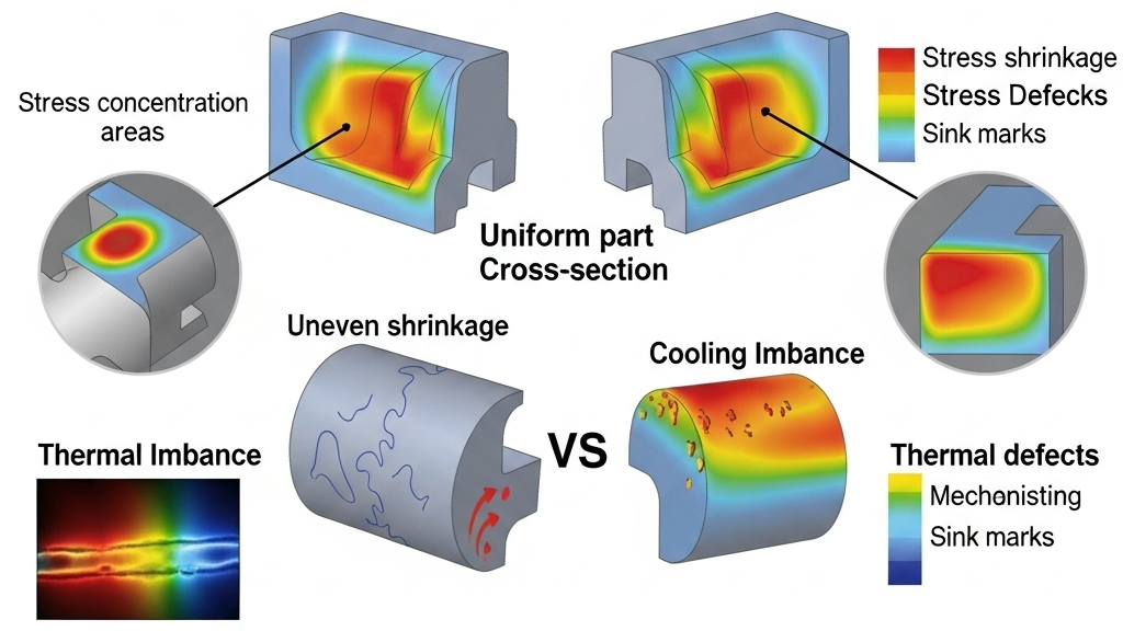
Checking a design before the tool is cut
A wall thickness check takes twenty minutes and prevents a tool modification that takes three weeks.
| Check | Method | Pass criterion |
|---|---|---|
| Wall map | Colour-code a wall thickness section through the part | No adjacent ratio above 1.5:1 |
| Corner review | Inspect every internal corner | Radius at least 0.5 × wall |
| Feature review | Ribs, bosses, snap fits, inserts | Ribs at 50 – 60%, bosses at 60%, cored |
| Flow path | Estimate fill from gate to furthest thin section | No thin section at the end of flow |
| Cooling balance | Compare thick and thin regions | Cycle time set by thickest section is acceptable |
| Mould flow analysis | CAE fill and pack simulation | No short shot, sink under 0.05 mm |
Mould flow analysis is the cheapest insurance available for a part with any wall variation at all. Our article on co-injection structures shows how wall design changes when the section is deliberately layered, and the general defect catalogue is in our injection moulding defects guide.
How wall thickness interacts with shrinkage and tolerance
Shrinkage values are quoted for a nominal wall. Change the wall and the shrinkage changes with it, which is why a part with three different wall thicknesses cannot be compensated with one number.
| Situation | Effect on final dimension |
|---|---|
| Uniform wall, stable grade | Shrinkage predictable, tolerance achievable |
| Wall varies 1.2:1 | Shrinkage varies 0.1 – 0.2%, manageable |
| Wall varies 1.5:1 | Shrinkage varies 0.3 – 0.5%, needs tight process control |
| Wall varies 2:1 or more | No reliable compensation; tolerance cannot be guaranteed |
The shrinkage data itself is in our shrinkage chart by material, the tolerance side is in the tolerance chart guide, and the PP-specific case is covered in reducing shrinkage in polypropylene. Concave and convex geometry adds its own cost effects, treated in concave versus convex design, and the full material context is in our injection moulding materials overview.
Material and thermal data in this guide follows the test methods published by ASTM International and ISO, with typical values cross-checked against MatWeb and Engineering Toolbox. Design and processing practice reflects Plastics Technology guidance and PLASTICS industry standards, with material characterisation maintained through SPE and NIST reference data. For the polymer chemistry, see injection moulding.
Why is uniform wall thickness so important?
Because thick sections cool last and keep shrinking while thin sections are already rigid. That mismatch produces sink marks on the surface or warpage in the part, and neither can be corrected afterwards without changing the tool.
What wall thickness ratio is acceptable?
1.2:1 between adjacent walls is ideal, 1.5:1 is the practical maximum. Above 1.5:1 a visible sink or measurable warp is almost certain, whatever the process settings.
How much does wall thickness affect cycle time?
Cooling time follows the square of wall thickness. Going from 2 mm to 4 mm quadruples cooling time, so one thick section can double the cycle time of the whole part.
Can I fix a thick section with packing pressure?
Only partly. Higher packing recovers roughly 0.05 to 0.15 mm of sink, but it cannot remove internal voids or correct a 1 mm wall step. Core out the thick section instead.
What is the best way to transition between two wall thicknesses?
A gradual taper of 3:1 to 4:1 (length to thickness difference). Avoid sharp 90° steps, which cause flow hesitation, sink marks and stress concentration.
Should ribs and bosses be the same thickness as the wall?
No. Ribs should be 50 to 60 percent of nominal wall and bosses 60 percent, with a radiused base and supporting gussets. Full-thickness ribs guarantee a sink mark on the opposite face.
Conclusion
Wall thickness is decided in the first hours of a design, and it governs the tool, the cycle time, the scrap rate and the field reliability of the part. A uniform wall with 1.2:1 transitions and cored thick sections is not a refinement — it is the baseline that makes everything else possible.
At Rui Cheng we review wall thickness, rib and boss design before quoting, and we run mould flow analysis on parts with any significant variation. Send us the drawing and we will come back with a design review, a material recommendation and an indicative part cost.